Motor service & repair, Figure 16, Figure 15 – Alamo HYDRO 15 User Manual
Page 50: Motor dis-assembly caution
HYDRO 15 (Service Manual) 09/06
© 2006
Alamo Industrial
Section 3 - 12
Figure 16
12345678901234567
12345678901234567
12345678901234567
12345678901234567
12345678901234567
12345678901234567
12345678901234567
12345678901234567
12345678901234567
1234567890
1234567890
1234567890
1234567890
1234567890
1234567890
1234567890
1234567890
1234567890
1234567890
1234567890
1234567890
1234567890
1234567890
1234567890
1234567890
1234567890
1234567890
1234567890
1234567890
1234567890
1234567890
1234567890
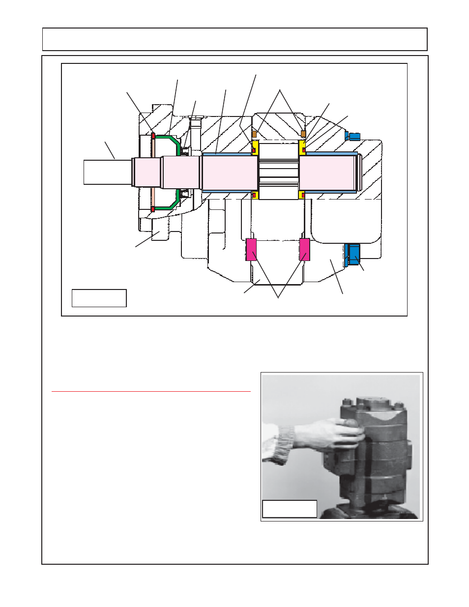
Shaft &
Gear Set
(Drive gear
& Driven
Gear)
Snap Ring
Seal Retainer Cup
Input Seal
Bushing (2)
Channel Seal (2)
SquareHousing Seal
Channel Seal
(2)
Thrust Plate (2)
Shaft End Cover
Dowel Pins (4)
Retaining Bolt &
Washers (4)
Port End Cover
Gear Housing
Figure 15
MOTOR SERVICE & REPAIR
Shown above (figure 15) is a general breakdown of the motor components, The motors are basicaly the
same in design and replace componetn procedure. Each motor will asemble different as some of the compo-
nents are different. Refer back to figure 15 for later motor assembly information
Motor Dis-Assembly CAUTION! :
Important information - read before dis-assembly:
1.
If prying off sections becomes necessary, take
extreme care not to mar or damage machined sur-
faces. Excessive force while prying can result in
mis-alignment and seriously damage parts.
2.
If sections of motor are difficult to come apart
during dis-assembly, tap gently with a soft hammer
(never use an iron hammer).
3.
Gears are closely matched, therefore they must
be kept together as sets when removed from the
pump. Handle gears with care to avoid damage to
journals or teeth. Avoid touching gear journals.
4.
Never hammer bushing into bores: always use
an arbor press.