Spindle assembly - service & repair, Figure 26 – Alamo HYDRO 15 User Manual
Page 71
Section 4 - 7
HYDRO 15 (Service Manual) 09/06
© 2006
Alamo Industrial
Figure 22
Figure 23
Figure 24
Figure 25
SPINDLE ASSEMBLY - SERVICE & REPAIR
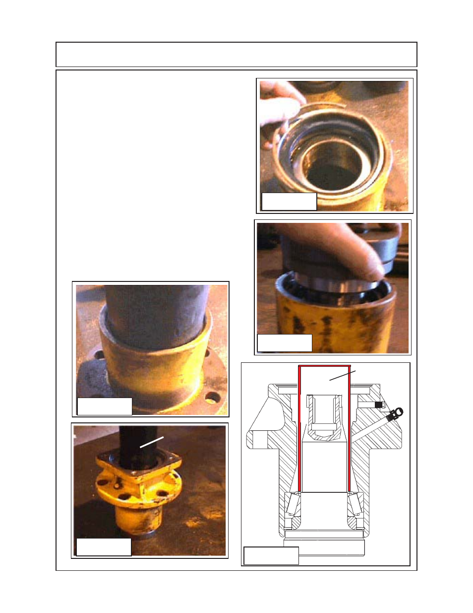
5.
Place the spindle shaft with the bearing ring
installed into the spindle housing. Turn the assembly
over so that the housing is sitting upright and the
spindle shaft is supporting the housing.
(figure 24 &
25)
. Make certain to support the spindle housing to
keep it straight up as the lower bearing ring is being
inserted into the seal as the lower bearing is being
driven down onto the shaft
(figure 26).
Use the 2-3/4”
16 gauge tubing to drive the lower bearing down onto
the bearing ring
(figure 26).
.
MAKE CERTAIN THAT
THE BEARING IS FULLY SEATED ONTO THE
SPINDLE
. If the bearing ring is not seated, or if
the bearing is not properly seated against the
bearing ring, the assembly will lose bearing
preload and rapidly fail
(figure 25).
6.
Remove the 2-3/4" 16 gauge pipe from the spindle
housing. Check to make certain the shaft, bearing ring
and lower bearing are seated properly. Install the
upper bearing cup using proper size driver. Make
certain the bearing cup is seated completely into the
spindle housing
(figure 26 & 27).
2-3/4” 16 gauge
tubing 8” long
1234567890123
1234567890123
1234567890123
1234567890123
1234567890123
1234567890123
1234567890123
1234567890123
123
123
123
123
123
123
123
123
123
123
123
123
123
123
123
123
123
123
123
123
123
123
123
123
123
123
123
123
123
123
123
123
1234567890123
1234567890123
1234567890123
1234567890123
1234567890123
1234567890123
1234567890123
1234567890123
1234567890123
1234567890123
1234567890123
1234567890123
1234567890123
Figure 26
2-3/4” 16 gauge
tubing 8” long