Motor service & repair, Motor cleaning & removal, Figure 8 motor information – Alamo HYDRO 15 User Manual
Page 46: Figure 9
HYDRO 15 (Service Manual) 09/06
© 2006
Alamo Industrial
Section 3 - 8
MOTOR SERVICE & REPAIR
Motor Cleaning & Removal:
1.
Clean Motor, Hoses and all connections before discon-
necting any components from the motors. This will keep con-
tamination from getting into system, (in this illustration the
mower is new, clean and un-used). Some type of drain pan
will be required to catch the oil that will drain out when hoses
are dis-connected. The hoses will need to be capped (plugged)
after being disconnected. If cap is not leak proof then hoses
must remain elevated above hydraulic tank to prevent oil leak
age from hose fittings.
The Center Motor and the Wing motors are built different
and will look different. The easiest way to ID which is which is
by the four bolts that hold the motor together. On center motor
the bolts are in the open as shown
(figure 9)
, on the wing motors
they are down inside a machined hole on the Port End Cover
(figure 10, 11 & 12).
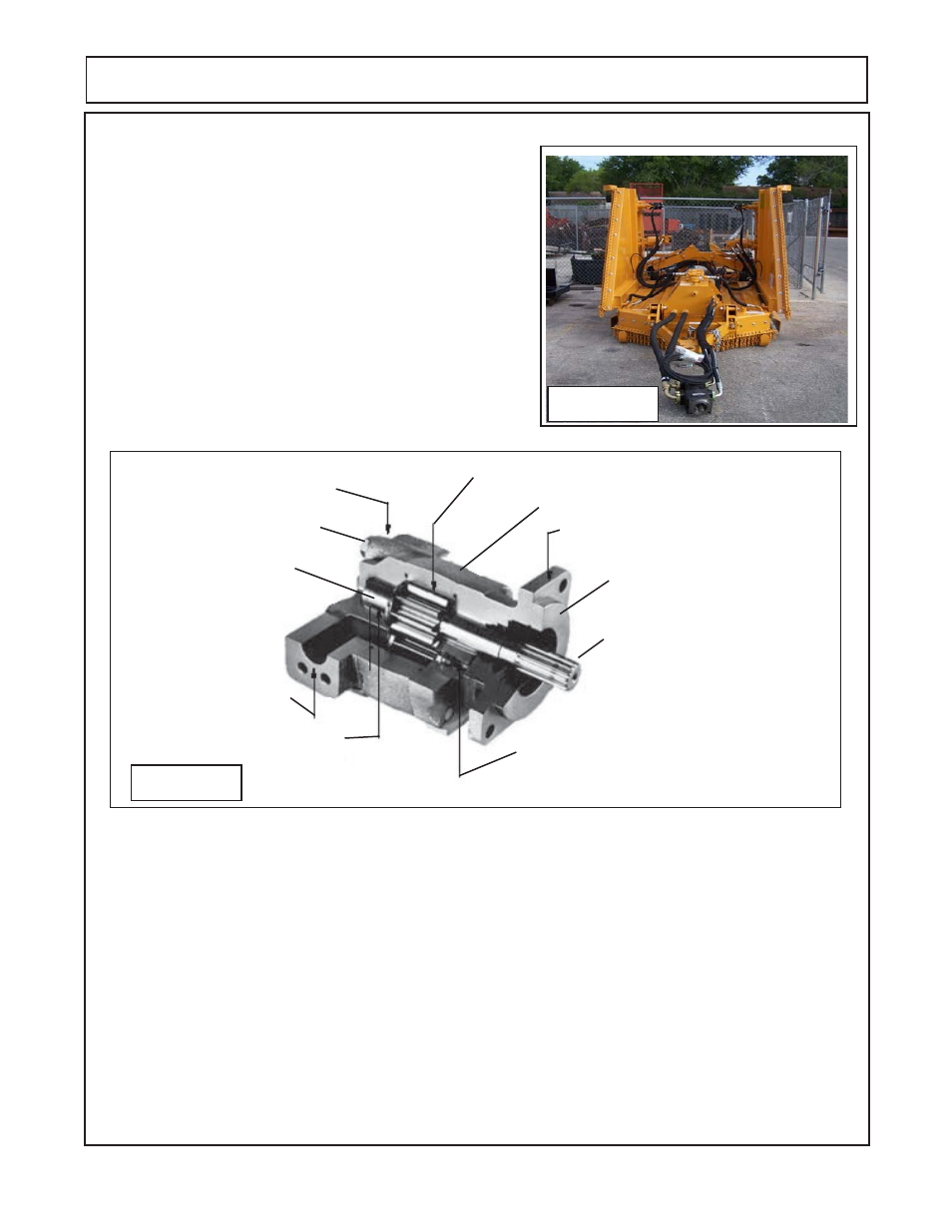
Figure 8
Motor Information:
Center.
Center motor is very different from the wing motors in design. The Housings are more square than the wings.
The manifold blocks are different, the center is thinner and will not use the solenoids that the wings do. The
four assembly bolts on the center motor are visible under manifold block.
(figure 10)
The center motor is
assembled to turn in a CW rotation which should be marked on the motor mounting flange from the factory.
The rotation is determined by standing on the deck behind the motor facing forward. Make certain which motor
is being serviced, Most parts will not interchange between the cent and wing motors.
RH Wing:
The RH wing motor is basically the same as the LH wing motor with the exception of the Port end cap is
installed different
(figure 11)
. The wing motor the four assembly bolts are in a machined hole under the manifold
block. The manifold block will need to be removed to see them. The RH Wing motor is assembled to turn in
CW rotation which should be marked on the motor mounting flange from the factory. The rotation is determined
by standing on the deck behind the motor facing forward. On the wing motor the fourassembly bolts are
in a machined hole under the manifold block. Make certain which motor is being serviced,
Iron Housing
Gear Set (Matched Set)
4 Bolt Mounting Flange
Port End Cover
Split Flange
2 on center motor
1 on each wing motor
High Temperature Seals
Low Friction Bushing Casting
Splined Input Shaft
Bolt & Lockwashers
Drive Gear w/Shaft &
Driven Gear
Figure 9
CENTER SECTION MOTOR SHOWN
Gear Housing
Shaft End Cover