Pump service & repair, Pump assembly caution, Figure 24 – Alamo HYDRO 15 User Manual
Page 32: Thrust plate caution! : (figure 24)
HYDRO 15 (Service Manual) 09/06
© 2006
Alamo Industrial
Section 2 - 16
Pump Assembly CAUTION! :
Important information - read before assembly:
1.
All sections have been cleaned and inspected, take extreme care not to allow the marring or
damage to machined surfaces to occur. Make certain all components are laid out so as not to
damage the machined surfaces.
2.
Make certain any replacement parts have been compared to the old parts to make certain they
are correct.
3.
Gears are closely matched, there fore they must be kept together as sets when removed from
the pump. Handle gears with care to avoid damage to journals or teeth. Avoid touching gear journals.
DO NOT mix new and old gears when reassembling pump.
4.
Never hammer bushing into bores: always use an arbor press, Hammering will damage
bushings and possibly the bores in the housing.
5.
(NOTE illustrations shown here are for a single pump, the tandem
pump is longer with more
sections, the disassembly will be basically the same with the exception tandem pump has two
pump section instead of one. See figure 9 & 10 for reference to components)
.
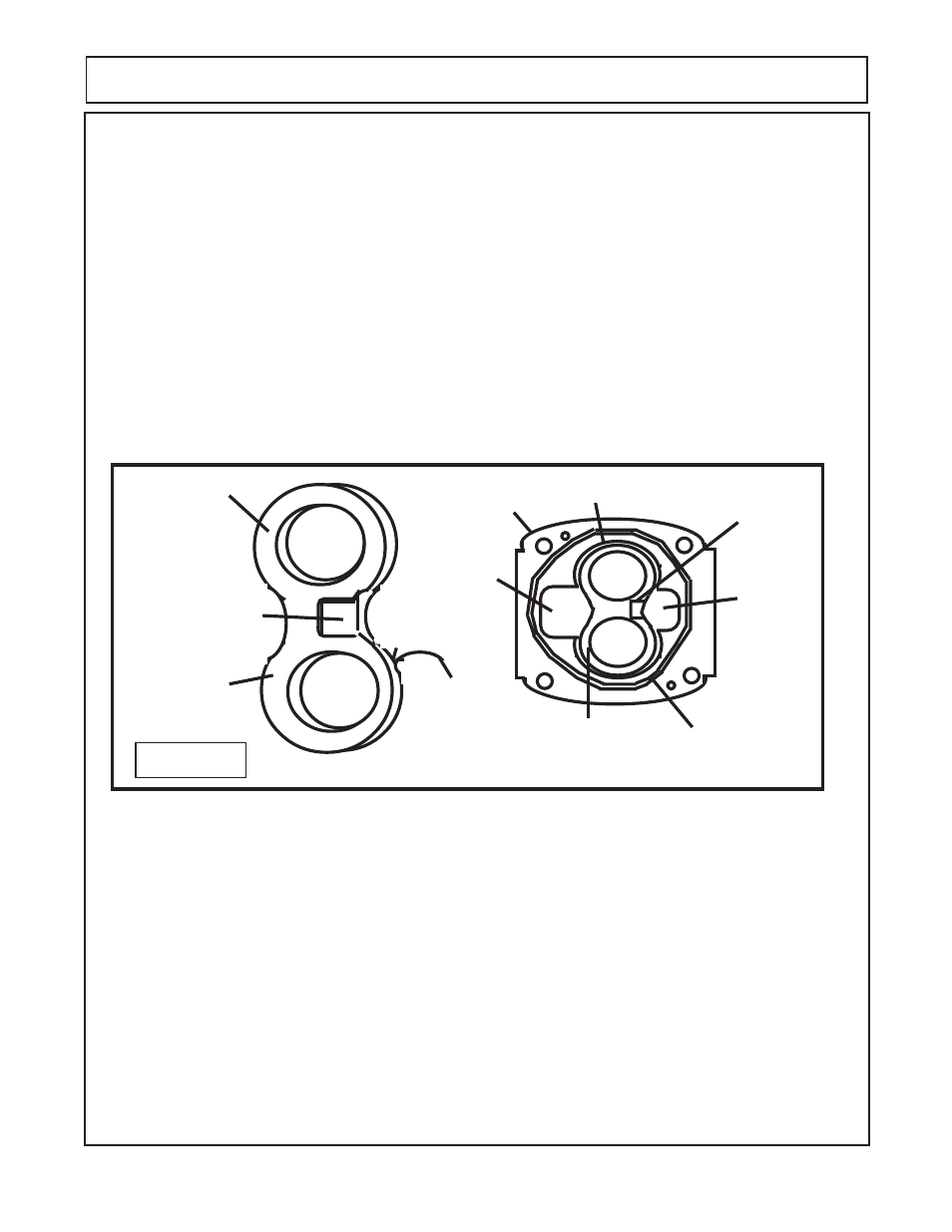
Gear Housing
Gear Bore
Gasket Seal
Outlet
(pressure)
Core
Opening
Relief Groove (High
Pressure)
Thrust Plate
Gear Side
(Smooth Side)
Channel
Seal Side
(Grooved Side)
Inlet
(Suction)
Core
Opening
Relief Groove (High
Pressure)
Thrust Plate
Installed in Gear
Housing
Figure 24
PUMP SERVICE & REPAIR
Thrust Plate CAUTION! : (Figure 24)
Important information - read before assembly:
1.
Thrust Plates must be in good condition, no scratches or excessive worn places on either side
of plate.
2.
Thrust plates must be installed correctly, The thrust plate has two surfaces, one surface has
a groove for the channel seal and the other surface is smooth with a relief groove (notch) in it.
3.
Thrust plate smooth surface with relief notch will always face the gears, the groove side for the
channel seal side will always face the gear bearing journal bushings never the gears as the gear
would destroy the channel seal.
4.
The relief groove will face the High Pressure side or Outlet Side of the gear housing. This is
determined by the port (bearing carrier or port end cap) port size. The Inlet (suction Side port will
have a bigger opening than the pressure side.
5.
These thrust plates are very important to the way they are installed. If they are installed wrong,
the pump will not function properly and other components could be damaged if operated with them
wrong.