Motor service & repair, Wing motor electric switches, Figure 48 – Alamo HYDRO 15 User Manual
Page 62
HYDRO 15 (Service Manual) 09/06
© 2006
Alamo Industrial
Section 3 - 24
MOTOR SERVICE & REPAIR
Recommended Start-Up Procedure For New Or Rebuilt Pump & Motor:
(Important Steps 26 through 30)
1.
Before installing a new or rebuilt pump or motor, back off the main relief valves until the spring tension on
the adjusting screw is relieved
(See Specification section for relief valve settings).
This will avoid the possibility
of immediate damage to the replacement pump in the event the relief valve has been set to high.
2.
Before connecting any lines (hoses) to the pump fill all the ports with clean oil to provide initial lubrication
on start up, fill the suction hoses with oil. This is particularly important if the pump is located above the reservoir.
Use thread sealant on all fittings and hose threads. DO NOT USE TEFLON TAPE.
3.
Make certain the oil reservoir is full of clean oil. Test oil before running a replacement pump. Contaminated
oil will damage a replacement pump even oil ran a minute or so. Review the type of failure that had occurred
and investigate any damage that may have been caused due to that failure.
DO NOT run the replacement pump
if the cause of the failure has not been corrected.
Any oil added to or to fill reservoir must be ran through a
100 micron screen before going into tank. See the tank fill section for available equipment for this purpose.
Never
run hot oil through a cold pump or motor, the hot oil will cause damage to the cold components
. Gradually warm
components by turning pump on then off, on then of until temperature is equalized.
4.
After connecting the lines (hoses) and mounting the replacement pump, operate the pump at least two
minutes at no load and at low RPM (400 rpm). During this break-in period, the mower should run free (no load)
and not develope an excessive amount of heat. If the unit operates properly, speed and pressure can then be
increased tonormal operating settings (See Specification Section).
5.
Reset the main relief if needed to its proper setting while the pump is running at maximum operating engine
(motor) speed for the PTO rating. (See Specification Section)
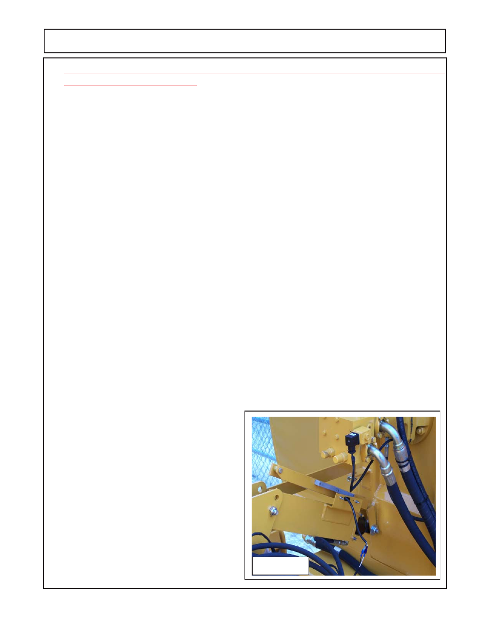
Wing Motor Electric Switches:
1
Wing Motors are equipped with electrical solenoids located it the motor manifold blocks, these are designed
to function with magnetic switched on brackets that are connected to the wing lift cylinders. The wings are
designed through these solenoid switches to turn the motors off when the wing is raised to a set angle. The
motors are also equipped with hydraulic brakes that are designed to speed the time it takes to stop the motor,
these also work through the motor manifold block.
(figure 48 LH Wing Shown)
2.
The Center Section Motor is controlled by engaging or dis-engaging the tractor PTO.
3.
Any time motors are being started the tractor
RPM should be reduced during start-up of motors.
Figure 48
4.
Cylinder Switch Brackets bolt to cylinder with a
U-Bolt and the cylinder mounting bolts
(figure 49 RH
Wing Shown)
. The switches and magnetic pickups
will bolt to the cylinder bracket. The Switch will have
two wires a white wire and a black wire. The wires will
have a female spade connector on the black wire
which will connect to the black/white wire on the wire
harness
(figure 50).
The switch white wire will have a
male spade connector which will connect to the white
wire of the wire harness
(figure 50).
5.
The leads to the tractor are to be connected with
the
positive 12 volt negative ground source
that is only
activated when the tractors ignition key is on. If it is
connected to a constant power source it will run the
Continued Next Page