Motor service & repair, Figure 19, Motor dis-assembly – Alamo HYDRO 15 User Manual
Page 51: Figure 17 figure 18
Section 3 - 13
HYDRO 15 (Service Manual) 09/06
© 2006
Alamo Industrial
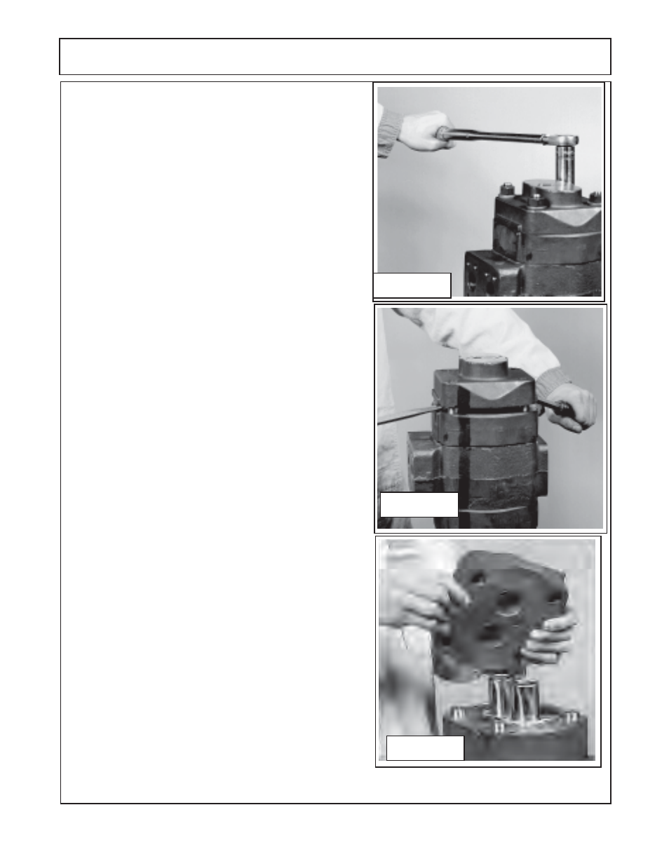
Figure 19
MOTOR SERVICE & REPAIR
Motor Dis-Assembly:
1.
Place the motor in a vise with the drive shaft pointing down.
Caution
DO NOT
grip on or near any machined surfaces of
motor during assembly or dis-assembly. Mark all sections of
the motor
(figure 13, 14 & 15)
, these marks must be done in
a manner that will not wash off . These marks are to identify
the orientation of the component of the motor later for re-
assembly. It is recommended that marks be done with metal
stamps that will mark components for correct assembly order
for & during re-assembly. This is
very important
as if any of the
sections of motor are installed in the wrong direction it could
damage motor when re-assembled or when motor is en-
gaged during operation
(figure 15).
(Remove the four bolts that
retain the manifold block to the top of the motor. There are O-
rings under the manifold blocks, check to make certain all of
these are removed and not stuck to one of the components.
(figure 13 & 14)
2.
Use a socket Wrench or Boxed end wrenches
(Air impact
wrenches are not recommended for dis-assembly).
Remove
the four hex bolts and washers
(figure 16)
, This will allow for
the removal of the port end cover of the motor. Inspect the bolts
for thread condition. If bad threads on bolts most likely the
threads in that hole are bad, mark the hole so it can be check
later.
3.
Lift the first port end cover
(figure 18)
, if prying is nec-
essary, be careful not to damage the machined surfaces
(figure 18)
. Dowel pins
(figure 19 )
will remain in either the
port end cover or gear housing. This will be OK because the
components must be re-assembled in the same direction and
orientation as removed. If one or more of the components are
to be replaced as parts then it may require that the dowel pins
be removed
(figure 19).
4.
Remove the thrust plate
(figure 19)
. Make a note how this
was removed, there is a smooth side and there is a grooved
side. The smooth side will always face the gears, the grooved
side will be for the channel seal
(figure 19 ).
Inspect the thrust
plate for damage or wear at this time
(see wear tolerance
chart
for pump and motors in this section)
, this will help in looking
for other wear or damage to other components and also enable
you to start making a list of components that need replacing.
5.
The channel seal will fit into a grove on the thrust plate,
this groove is all the way around and on both sides of the shaft
(Note a Pump channel seal in only on one side)
(figure
20).
The Thrust plate is flat on one side with two relief notches. The
flat side of the thrust plate with the relief notches will always
face the gears. The relief notches will be the same and can
be installed with either notch to either port, check to make
certain when these are removed that they were installed cor-
rectly.
Figure 17
Figure 18