Motor service & repair – Alamo HYDRO 15 User Manual
Page 58
HYDRO 15 (Service Manual) 09/06
© 2006
Alamo Industrial
Section 3 - 20
Figure 37
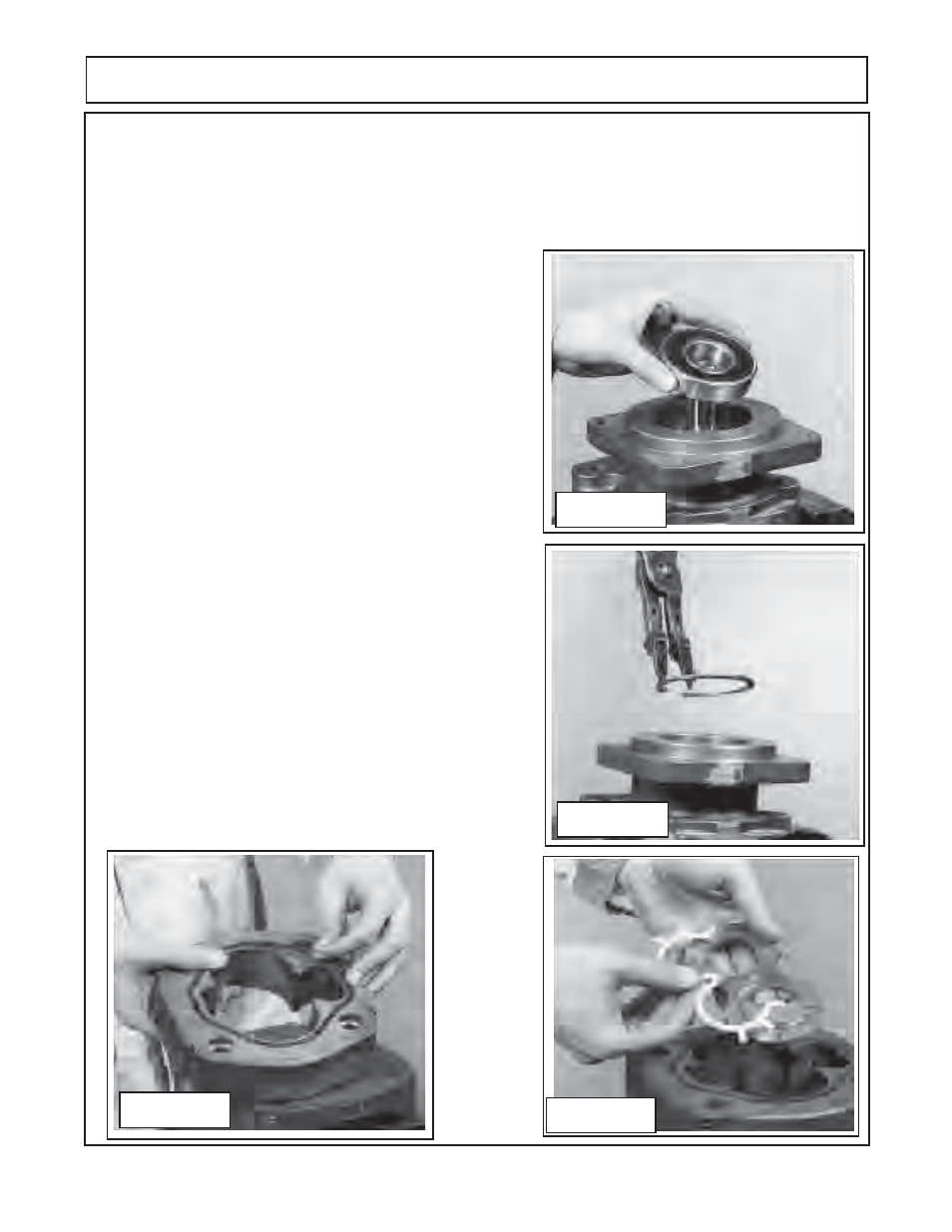
Figure 34
Figure 35
Figure 36
MOTOR SERVICE & REPAIR
12.
Assemble the channel seals
(figure 37 & 38)
into the
grooves in the thrust plates
,
with the flat side of the seal
facing away from the thrust plates as shown
(figure 37 &
38).
IMPORTANT NOTE:
Channel seals will always be on
side of thrust plate away from gears, only the smooth side
of thrust plates are against gears. The channel Seals will
be all around gear shaft journal opening on motors.
13.
Gently slip the thrust plate
(figure 39)
into the gear housing
and into place on the shaft end cover
(figure 39).
The channel
seal from
step 13
should face the shaft end cover. The relief
grooves in the thrust plate should face the outlet gears
figure
39).
14.
Coat the driven gear journal with light coat of oil, Slide the
driven gear
(figure 40)
through the housing and into the bushing
in the shaft end cover
(figure 40)
Coat the drive gear
splined
shaft end with light coat of grease, insert shaft into the
special steel sleeve
(figure 7 recommended tools list)
. Lightly
seal. Remove steel sleeve, squirt clean oil over gears
(figure
40)
.
Note
purpose of sleeve is to prevent splines on the shaft
from damaging double lip seal. Coat the steel sleeve with
grease. Place the lightly greased drive gear shaft inside the
sleeve and slide both through shaft end cover with a twisting
motion until the integral gear rest against thrust plate. Avoid
damaging double lip seal. Remove steel sleeve, squirt clean
oil over gears
(figure 40)
.
Note
purpose of sleeve is to prevent
splines on the shaft from damaging double lip seal.
10.
Using the snap ring pliers as shown. Install the snap ring into the flange side of the shaft end cover
(figure
35).
Lightly tap the snap ring with a small punch and hammer to make certain it is seated into the snap ring
groove of the shaft end cover.
11
Remove the shaft end cover
(figure 36)
from the vice and turn it over 180° and re-insert it into the vise with
the splined side down and re-insert it into the vise. Grease the new Gasket Seals
(figure 15)
and insert
it in both sides of all gear housing. Position the gear housing
(figure 36)
onto the shaft end housing
(figure
35)
aligning it with the holes for the dowel pins.
Tap it with a soft hammer until it rest tightly against the
shaft end cover.
Be careful not to pinch the seal gasket
(figure 36).