Pump service & repair, Recommended tools, Figure 4 – Alamo HYDRO 15 User Manual
Page 23: Figure 5, Figure 6, Figure 7
Section 2 - 7
HYDRO 15 (Service Manual) 09/06
© 2006
Alamo Industrial
PUMP SERVICE & REPAIR
Recommended Tools:
Listed below are some of the toolds that
are recommended for the dis-assembly and re-
assembly of the pump for the HYDRO 15 Mower.
1.
Arbor Press
2.
Awl
3.
1-1/2" Dia steel ball
4.
Bearing Puller (Owaonna Tool Co.
MD-956 or equivalent)
5.
Bushing Remover Tool (figure 4)
6.
Clean lintless Cloth
7.
Deburing Tool (an old file with cutting
teeth ground off)
8.
Machinest Hammer
9.
Soft Hammer
10. Permatex Aviation Form-A-Gasket.™
(No. 3 non hardening sealant or equal)
11. Medium Grit Carborundurn Stone.
12. Seal removal Tool (figure 6)
13. Oil and Grease
14. Snap Ring Pliers
15. Prick Punch
16. Bushing Installation Tool (figure 5).
17. Scale (1/32" or 1/64" graduations)
18. Small Screw Driver
19. Torque Wrench (in. lbs & ft lbs)
20. Vise with 6" minimum opening
21. Bar for Lip Seal Installation
For Front (Wing Supply) Pump
use 1-3/4" dia X 2" Bar
For Rear (Center Supply) Pump
use 2-1/2" dia X 2" Bar
22. Special Steel Sleeve (figure 7)
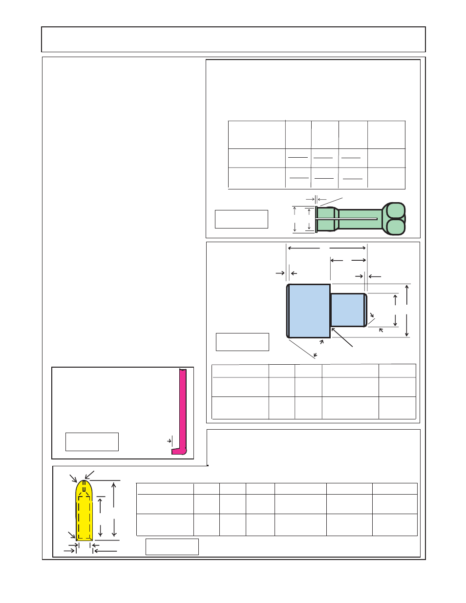
Bushing Puller: The bushings in the pump may be
removed from tier bores, using blind hole collet-type bushing
pullers similar to those manufactured by Owatonna Tool Co. The
Table below illustrates the modification necessary to adapt the
OTC collets to this task. Equivalent pullers from other suppliers
may be modified in a similar fashion.
Pump
A
B
C
Make
f/ OTC
Collet No.
Wing Supply
Pump
.980
.970
.875
Ref
.100
.090
33863
Center Supply
Pump
1.382
1.372
1.260
1.250
.100
.120
33865
Figure 4
.015 R Maximum
C
A
B
30°
30°
C
D
B
.06
.06
A
Grind Relief Allowable
Surface
Finish
32
Bushing Installation
Tool A.I.S.I 8620
Bearing Qaulity
Steel Heat treated
Figure 5
Seal Removal Tool: Easily
made from old screw driver.
Heat the tip and bend as
shown. Grind the tip to fit the
notch behind the shaft seal.
1/4"
Figure 6
Special Steel Sleeve: The special steel sleeve is used to insert the
drive shaft through the lip seal without damage and can be made
from bar stock. For the center supply pump use a 1-1/8" to 1-1/4"
dia X 4-5/8" bar. For wing supply pump use a 1-1/2" dia X 4-5/8" bar.
The drawing and cgart give details for making this special tool.
C Rad
1/4" Hole Drill through
A
B
F°
E
D
Pump
A
B
C dia.
D dia.
Wing Supply
Pump
1.47
1.054
1.250
Center Supply
Pump
3.00
+ .000
- .002
3.00
1.73
1.492
+ .000
- .002
1.750
Figure 7
Pump
A
B
C Rad
F° Chamfer
Wing Supply
Pump
4-1/2"
1.065
.015" X 45°
Center Supply
Pump
3-3/8"
+ .000
- .002
3-3/8"
4-1/2"
1.250
9/16"
D Rad
E dia.
1.002 + .002
- .000
9/16"
1.377
+ .000
- .002
+ .002
- .000
.015" X 60°
All external surfaces MUST be free of scratches and burrs