Speed increaser service & repair, Figure 11 – Alamo HYDRO 15 User Manual
Page 122
HYDRO 15 (Service Manual) 09/06
© 2006
Alamo Industrial
Section 7 - 12
Speed Increaser Service & Repair
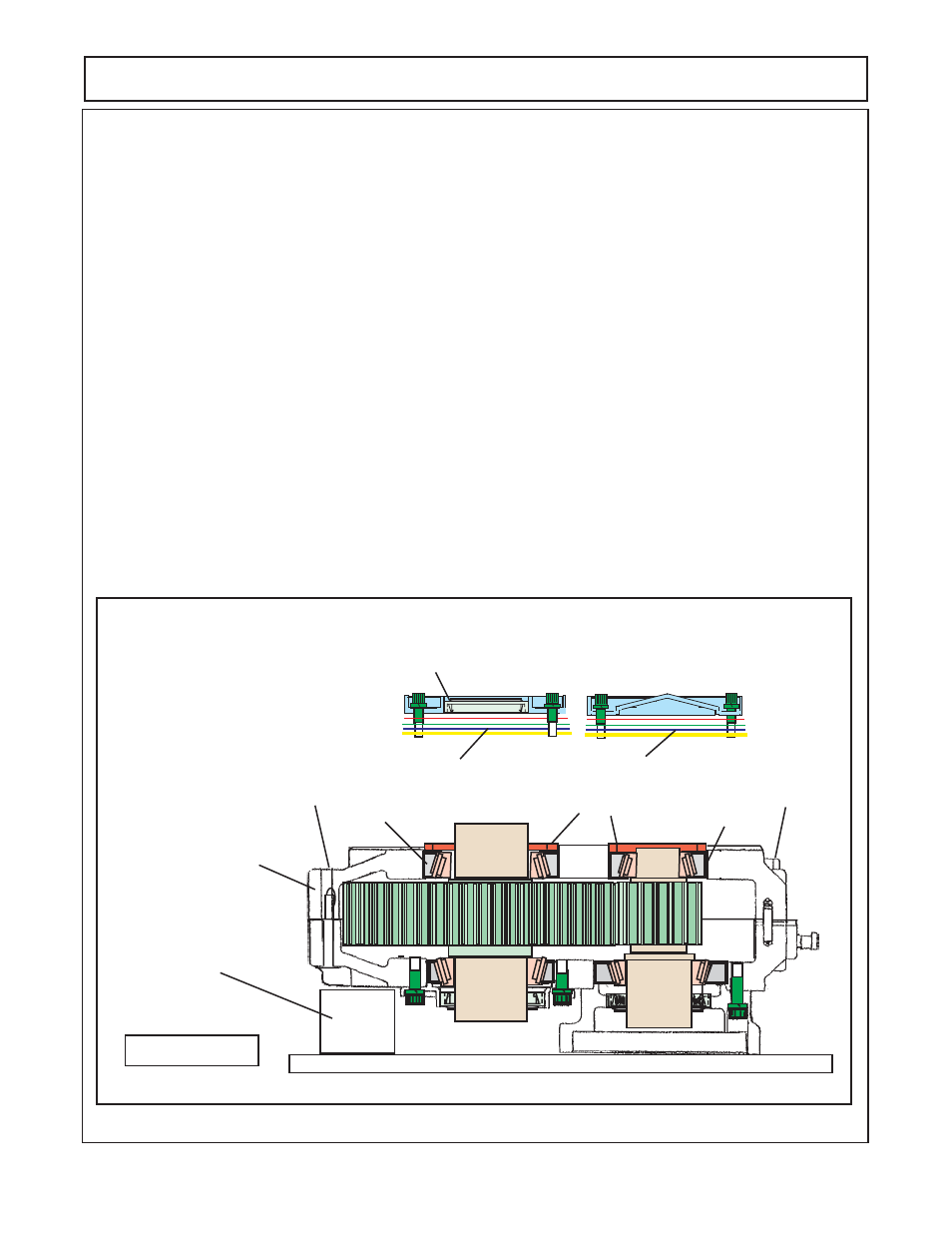
7.
Install the PTO side of housing half
(figure 4 item 15)
. Male certain old gasket has been removed and
gasket face of housing is clean. Aligning the dowel pins
(figure 4 item 17)
between the two housing halves the
PTO side Housing half down over the pump side housing half. It make require a soft hammer to tap the two
halves together. When two halves are together check to make certain gasket has not slipped out. Insert the 8
hex bolts
(figure 4 item 31)
into the 8 holes in the housing halves from the PTO side
(figure 11)
. Install the
Lockwashers and Hex Nuts
(figure 4 item 32 & 33)
onto the 3/8" bolts. Tighten the bolts and nuts in an
alternating pattern and in increments until bolts are snug. Torque the bolts in the same pattern until they are
torqued to 21 to 25 ft lbs.
8.
Install the bearing Cups
(figure 4 items 13 & 19)
the bearing cone
item 13
is smaller than the other 1 and
will only fit the PTO side of the small gear shaft. Bearing cups should be seated against bearing cone at gear
(figure
11). Use only soft hammer and light force to install bearing cups in housing half.
9.
Install the bearing Spacer
(figure 4 item 11 & 35).
The smaller bearing spacer ring goes on the small gear
shaft
(figure 11).
The larger bearing spacer ring goes on the large gear shaft
(figure 11).
10.
Install the second open cover
(figure 4 item 9)
and the closed cover
(figure 4 item 7).
Make certain the ID
of the seal in the open cover is coated with a light coat of grease. The closed cover and the open cover will
require that the shims
(figure 4 items 21, 22, 23, 24, 25, 26, 27 & 28). The amount of shims required will vary.
It is recommended to try to start with the amount that was removed during dis-assembly.
The purpose of the
shims is to set the end play in the bearings and gear shafts
. Add or remove shims as required until the end
play in the gear shaft (Large and Small) is from .007" to .011". The open cover and the closed cover retaining
bolts will need to be torqued 12 to 15 ft lbs. Torque these in an alternating pattern
(figure 11).
123
123
123
123
123
123
123
123
12
12
12
123456789012345
123456789012345
123456789012345
123456789012345
123456789012345
123456789012345
123456789012345
123456789012345
123456789012345
123456789012345
123456789012345
123456789012345
123456789012345
12345678901234567890123456789012123456789012345678901234567890121234567890123456789012345678
12345678901234567890123456789012123456789012345678901234567890121234567890123456789012345678
12345678901234567890123456789012123456789012345678901234567890121234567890123456789012345678
12345678901234567890123456789012123456789012345678901234567890121234567890123456789012345678
FIGURE 11
Sitting on Block to Make
it Sit on Table Level
PTO Side Housing Half
Insert Hex Head 3/8" Bolt
Washer & Nut
Insert Hex
Head
3/8" Bolt
Washer
& Nut
Bearing Cone
Bearing Cone
Bearing Spacer
12
12
12
12
123
123
123
123
123
123
123
123
123
123
123
Various Shims
Various Shims
Open Cover w/ Seal Installed
Closed Cover