Speed increaser service & repair, Figure 12, A" "b" figure 13 – Alamo HYDRO 15 User Manual
Page 123: Re-assembled speed increaser
Section 7 - 13
HYDRO 15 (Service Manual) 09/06
© 2006
Alamo Industrial
Speed Increaser Service & Repair
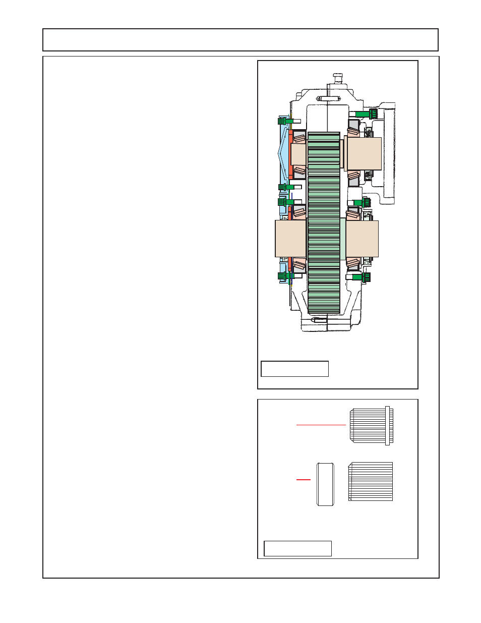
FIGURE 12
123
123
123
123
123
123
123
123
1234
1234
123
123
123
123
123
123
123
11.
Reinstall the plugs bag into the correct holes that
they were removed from
(see Part Manual for
holes to
be plugged)
Use pipe sealer for plug,
DO NOT
use teflon
tape.
12
Refill speed increaser with oil, Check the Oil level in
the speed changer Use a recommended grade of oil. A
recommended grade is
SAE 90W oil with E.P. Additive.
Most speed increaser are installed where the pump will
mount above the PTO (figure 1) but in some case it may
require the pump be mounted below the PTO shaft
height. If this is the case the breather plug will need to
be installed in a different location on one of the side
plugs. Normal fill level is the setscrew plug about 1/3 of
the way up on the side of the housing. If Speed in
creaser is turned to the bottom opposite what is shown
in figure 1 the level plug will be the one that was on the
bottom before and would be just below the center line of
the bearings
(figure 3)
13.
Install the splined pump shaft adapter. There are
two types of splined pump adapters that were used.
While either style can be used the components of each
style can not be mixed or left out. Make note of which
style that is being used.
"A"
= Old Style Splined adapter: See figure 1 drawing "A"
.
The old style splined adapter has a snap ring groove
on the OD of it and a snap ring, This splined adapter
pushes into the speed increaser before the pump is
bolted on, the snap ring prevents the splined adapter
from sliding inward and outward inside speed increaser
is in operation.
DO NOT
use with out the snap ring on
splined adapter, failure will occur
(figure 2 & 13).
This
will only fit with the snap ring outward.
"B"
= New Style Splined Adapter: See figure 1 drawing "B"
.
The new style splined adapter
WILL NOT
have a snap
ring groove and
WILL NOT
use a snap ring to keep
adapter stationary during operation. The new style used
a tube type spacer that is slid into the speed increaser
and then the splined adapter is inserted. This tube
spacer will keep the splined adapter from sliding.
DO
NOT
use without the tube spacer installed,
failure will
occur
(figure 2 &13).
This must be installed with the
spacer tube insert first and then the splined adapter to
work properly.
14.
Connect Pump to Speed increaser, See pump
repair service section.
DO NOT
start pump until
looking at pump installation service repair start-up in-
structions.
NEVER
use Teflon tape on any hose or
fittings connections, only thresd sealer on pipe con-
nections.
"A"
"B"
FIGURE 13
Splined Pump Shaft Adapters,
Old & New Style
Re-Assembled
Speed Increaser