Optional axle level lift cylinder repair – Alamo HYDRO 15 User Manual
Page 103
Section 5 - 29
HYDRO 15 (Service Manual) 10/06
© 2006
Alamo Industrial
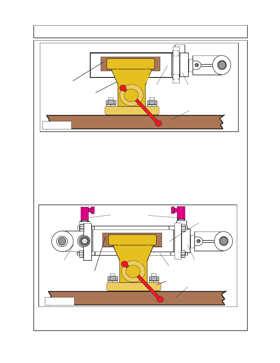
9.
Coat the cylinder base barrel seals
(figure 6 & 9 item 8)
with coat of hydraulic oil. Install the
cylinder base end into the barrel
(see figure 9)
. If plastic plug is installed in base end as shown
(see
figure 9)
it will allow the insertion of the base end into the barrel if plug is removed. Make certain
that the ports on the base end are aligned with thew cylinder head as shown
(see figure 9 item 8
& 9)
, the ports
must be aligned
this way.
10
Install cylinder tie-rods
(figure 9 item 6 & 7)
, make certain that the hex nuts that were left on
the tie-rod is loose. Insert the tie- rods
(qty 4)
and the hex nuts
(qty 8)
onto the tie-rods. The hex
nuts must be screwed on at the same rate and on each end, try to keep the same amount of threads
sticking out the nuts on both ends of the tie-rods. Snug the nuts down an all 4 tie rod evenly and
alternating as to keep the same torque evenly. Torque tie-Rod nuts to
80 ft. lbs. (based on 1/2” tie-
rod).
11.
Install theHydraulic Elbow Adapters into the cylinder head ports
(figure 9 item 8 & 9).
12.
Install the cylinder on mower, Mount cylinder with the base end
(figure 9 item 8)
to the deck lug.
Mount cylinder head / rod end
(figure 9 item 9)
to the axle lug.
OPTIONAL AXLE LEVEL LIFT CYLINDER REPAIR
1234
1234
123
123
Wood or other soft material
Bench Vise
Work Bench
9
(cyl head, clevis, cyl
rod & piston asy).
5
Figure 8
1234
1234
123
123
Wood or other soft
material
Bench Vise
Work Bench
9
(cyl head, clevis, cyl
rod & piston asy).
5
8
12
12
12
1234
1234
1234
12
12
12
12
6 & 7
12
12
12
123
123
123
123
123
123
12
12
Hydraulic Elbow
Adapters
Figure 9
1234
1234