Pump service & repair, Figure 8 – Alamo HYDRO 15 User Manual
Page 24
HYDRO 15 (Service Manual) 09/06
© 2006
Alamo Industrial
Section 2 - 8
PUMP SERVICE & REPAIR
3
1
2
4
5
6
7
Item
Qty
Description
1
1
Pump Assembly (Tandem Pump)
2
2
Split Flance Kit, (1" Flange)
1
O-Ring (for 1" Flange) (Qty Each Kit)
4
Bolt, Hex Head, (Qty Each Kit)
4
Lockwasher (Qty Each Kit)
3
2
Split Flance Kit, (1-1/2" Flange)
1
O-Ring (for 1" Flange) (Qty Each Kit)
4
Bolt, Hex Head, (Qty Each Kit)
4
Lockwasher (Qty Each Kit)
4
1
Hose Asy, 1" Hose & Flange (Pressure to Wing Motors)
5
1
Hose Asy, 1" Hose & Flange (Pressure to Center Motor)
6
1
Hose Asy, 1-1/2" Hose & Flange. (Suction Hose for Center Motor
7
1
Hose Asy, 1-1/2" Hose & Flange. (Suction Hose for Wing Motor)
Tandem Mounted Pump
Figure 9
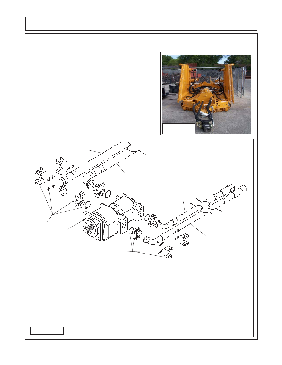
Pump Cleaning & Removal:
1.
Clean Pump, Hoses and all connections before discon-
necting any components from the pump. This will keep con-
tamination from getting into system. Figure 8 shows the pump
and hoses connected to the mower (this mower is new, clean
and un-used) with the pump sitting on the ground, if the hoses
are to be dis-connected, the pump should mounted up and
above the hydraulic tank (on work bench, hoist, etc.). What
ever the technician decides to mount pump on. Some type of
drain pan will be required to catch the oil that will drain out when
hoses are dis-connected. The hoses will need to be capped
(plugged) after removal being disconnected. If cap is not leak
proof then hoses must remain elevated above hydraulic tank to
prevent oil leakage from hose fittings. Figure 9 shows how the
hoses are connected. Hoses are connected with 4 bolt split
flange kits (1-1/2" on suction side &1" on pressure side)
Figure 8