Spindle assembly - service & repair, Figure 28 figure 29, Figure 27 – Alamo HYDRO 15 User Manual
Page 72
HYDRO 15 (Service Manual) 09/06
© 2006
Alamo Industrial
Section 4 - 8
10.
Tighten the new Lock Nut with a 4 prong socket and hand ratchet until tight Back the nut
off until 12 to 15 INCH POUNDS of rolling resistance is achieved
(figure 29).
11.
Use a punch to stake the bearing nut in place. Be sure to stake the nut at both slot
locations.
(figure 30).
12.
Useing the grease fitting to the side of the spindle housinf pump grease in to spindle
housing. Watch the upper bearing cone, when grease is being forced through the roller
bearings of the upper bearing cone spindle is full
(figure 31).
13.
Install the new motor flange gasket. Apply a thin film of silicone to both sides of the gasket
to ensure a good seal
(figure 31).
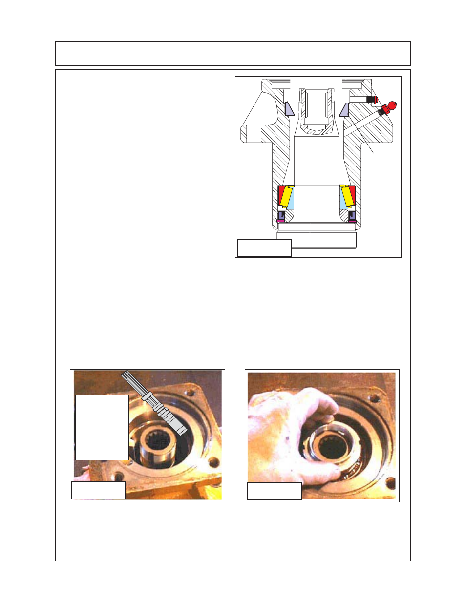
7.
Fill the spindle housing with
NLGI EP #
2 grease
Alamo Industrial PN 00900000
(figure
28).
The proper level will be up to the
upper bear cup bottom side for now,
do not
fill with grease
above the bottom of upper
bearing cup
, if you do it will interfere with
adjusting bearing preload.
8.
Pack the upper bearing cone with
grease completely. Install upper bearing
cone down over the top of the spindle shaft,
if needed use a bearing driver to seat
bearing cone into bearing cup
9.
Apply Locktite # 277
to the spindle
threads where the bearing nut screws on,
It may require grease to be cleaned off of
threads to apply locktite.
(figure 29) .
Start
the New Locknut onto the shaft threads,
the nut should start by hand, make certain
it is started straight.
(figure 29).
Figure 28
Figure 29
Use Grease
Gun to put
Grease into
Spindle, Fill to
bottom of
Upper Brg Cup
only for now.
SPINDLE ASSEMBLY - SERVICE & REPAIR
Figure 27
Upper
Bearing
Cup