Pump service & repair, Figure 16, Figure 17 figure 18 – Alamo HYDRO 15 User Manual
Page 28
HYDRO 15 (Service Manual) 09/06
© 2006
Alamo Industrial
Section 2 - 12
seal
(figure 10 item 7).
Inspect the thrust plate for damage or
wear at this time
(see wear tolerance
chart for pump and motors
in this section)
, this will help in looking for other wear or damage
to other components and also enable you to start making a list
of components that need replacing.
5.
Carefully remove the drive gear and the driven gear
(figure 10
item 15)
. Avoid tapping the gear teeth together or against other
hardened surfaces
(figure 15),
Keep these gears together
because they are a matched set. Examine the gears for wear
and/or damage. Note the dowels
(figure 15)
that are in the gear
housing, sometimes these will come out and be in the end cover
or they may stay in the gear housing. It will be OK as long as
the same components are to be reassembled, but if some
components are to be replaced and some are not then these
dowel pins will have to be re-moved and re-inserted.
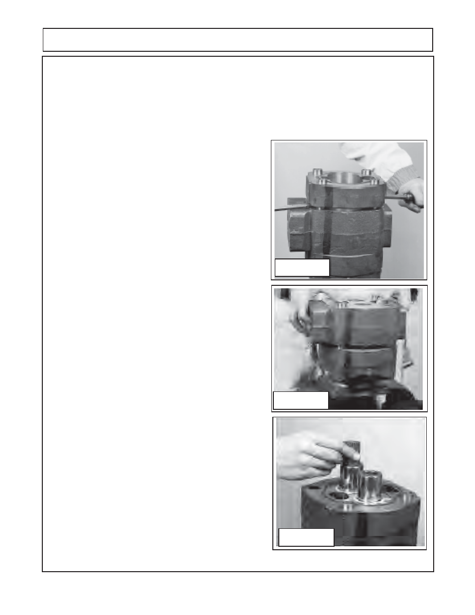
6.
Remove the outer gear housing (
figure 10 item 16)
. Lift the
outer gear housing
(figure 16)
up, if prying is necessary take
care not to damage machined surface. Examine gear housing
for wear and /or damage.
(See wear tolerance
chart for pump
and motors in this section).
When the gear housing is removed
there will be another thrust plate and channel seal
(figure 10
item 7 & 8)
that was under the gears, sometimes this thrust
plate will come out with the gears.
7.
Carefully lift or pry the bearing carrier
(figure 10 item 13)
off carefully to avoid damage to carrier
(figure 17)
. The dowel
pins will remain in the bearing carrier housing or the gear
housing, it will not require that they be removed unless the
housing is to be replaced and then only to arrange the dowel
pins order so the components will fit together.
8.
Remove the connecting shaft
(figure 10 item 14)
as shown
(figure 18)
by pulling it up out of the drive gear shaft splines.
Inspect the shaft for wear and /or damage. Inspect the end of
the drive gear. Remove the thrust plate, note the thrust plate
will have the channel seal in it
(figure 10 item 7 & 8)
. Note the
smooth side of thrust plate always goes toward the gear.
Care
fully remove the drive gear and the driven gear (figure
10 item 9)
.
Avoid tapping the gear teeth together or against other hardened
surfaces
(figure 18),
pull the drive gear straight up. The drive
gear has the splined shaft on the other end and care must be
taken not to hit the splined shaft against sides and damaging
them.Keep these gears together because they are a matched
set. Examine the gears for wear and / or damage
Figure 16
3.
Lift the first port end cover
(figure 10 item 17)
, if prying is necessary, be careful not to damage the machined
surfaces. Dowel pins
(figure 10 item 11)
will remain in either the port end cover or gear housing. This will be
OK because the components must be re-assembled in the same direction and orientation as removed. If one
or more of the components are to be replaced as parts then it may require that the dowel pins be removed
(figure 13).
4.
Remove the thrust plate
(figure 10 item 8)
. Make a note how this was removed, there is a smooth side and
there is a grooved side. The smooth side will always face the gears, the grooved side will be for the channel
PUMP SERVICE & REPAIR
Figure 17
Figure 18