Motor service & repair, Figure 22, Figure 21 figure 20 – Alamo HYDRO 15 User Manual
Page 52
HYDRO 15 (Service Manual) 09/06
© 2006
Alamo Industrial
Section 3 - 14
Figure 22
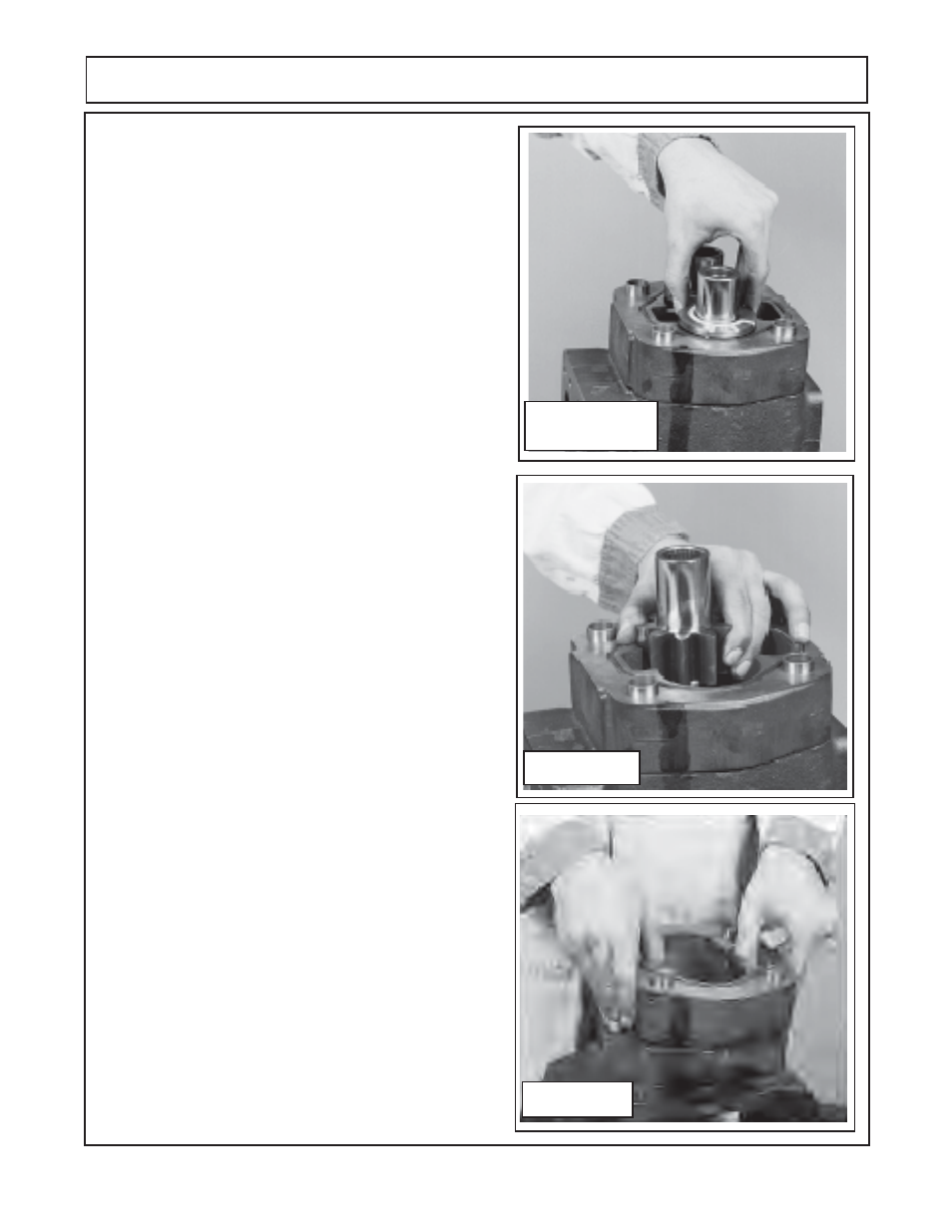
6.
Inspect the thrust plate for damage or wear at this
time
(see wear tolerance
chart for pump and motors in
this section)
, this will help in looking for other wear or
damage to other components and also enable you to start
making a list of components that need replacing.
(figure
25)
7.
Carefully remove drive gear and driven gear
(figure 21)
.
Avoid tapping the gear teeth together or against other
hardened surfaces
(figure 21),
Keep these gears together
as they are a matched set. Examine the gears for wear
and damage. Note the dowels
(figure 21 & 22)
that are in
gear housing, sometimes these will come out and be in
the end cover or they may stay in the gear housing. It will
be OK as long as the same components are to be
reassembled, but if some components are to be replaced
and some are not then these dowel pins will have to be re-
moved and re-inserted.
IMPORTANT! If working on center, LH & RH motor at
same time it is important not to mix the components of the
motors. Keep the Gears separated between the motors as
gears are matched sets. DO NOT mix used gears and new
gears a motor.
8.
Remove the second thrust plate
(figure 21)
, the 2nd
thrust plate is at the bottom of gear housing and is visible
after gears have been removed. Make a note how this was
removed, there is a smooth side and there is a grooved
side. The smooth side will always face the gears, the
grooved side is for channel seals. Inspect the thrust plate
for damage at this time
(see wear tolerance
chart for pump
and motors in this section)
. Note: Thrust plate can be re-
moved after gear housing if wanted
. (figure 25).
9.
Remove the gear housing (
figure 22)
. Lift the gear
housing up, if prying is necessary take care not to damage
machined surface. Examine gear housing for wear and /
or damage.
(See wear tolerance
chart for pump and
motors in this section).
10.
Remove shaft end cover
(figure 23)
from vice and turn
it 180° over and re-insert it into vice. Using snap ring pliers
remove the snap ring
(figure 23)
as shown.
11.
Remove the seal retainer cup
(figure 15)
The seal
retainer cup should pull up out of the end shaft cover. If it will
not go on to step 12 and remove the retainer cup with the
seal.
12.
Remove shaft end cover
(figure 10 item 4)
from vice and
turn it 180° over and re-insert it into vice. Remove the
double lip seal by inserting the special seal removal tool
(see figure 6 recommended tools).
Make note of which way
seal is removed. Inspect the shaft end cover seal seat area
(figure 24).
MOTOR SERVICE & REPAIR
Figure 21
Figure 20