Motor service & repair, Figure 13, Center motor only 4 – Alamo HYDRO 15 User Manual
Page 48
HYDRO 15 (Service Manual) 09/06
© 2006
Alamo Industrial
Section 3 - 10
MOTOR SERVICE & REPAIR
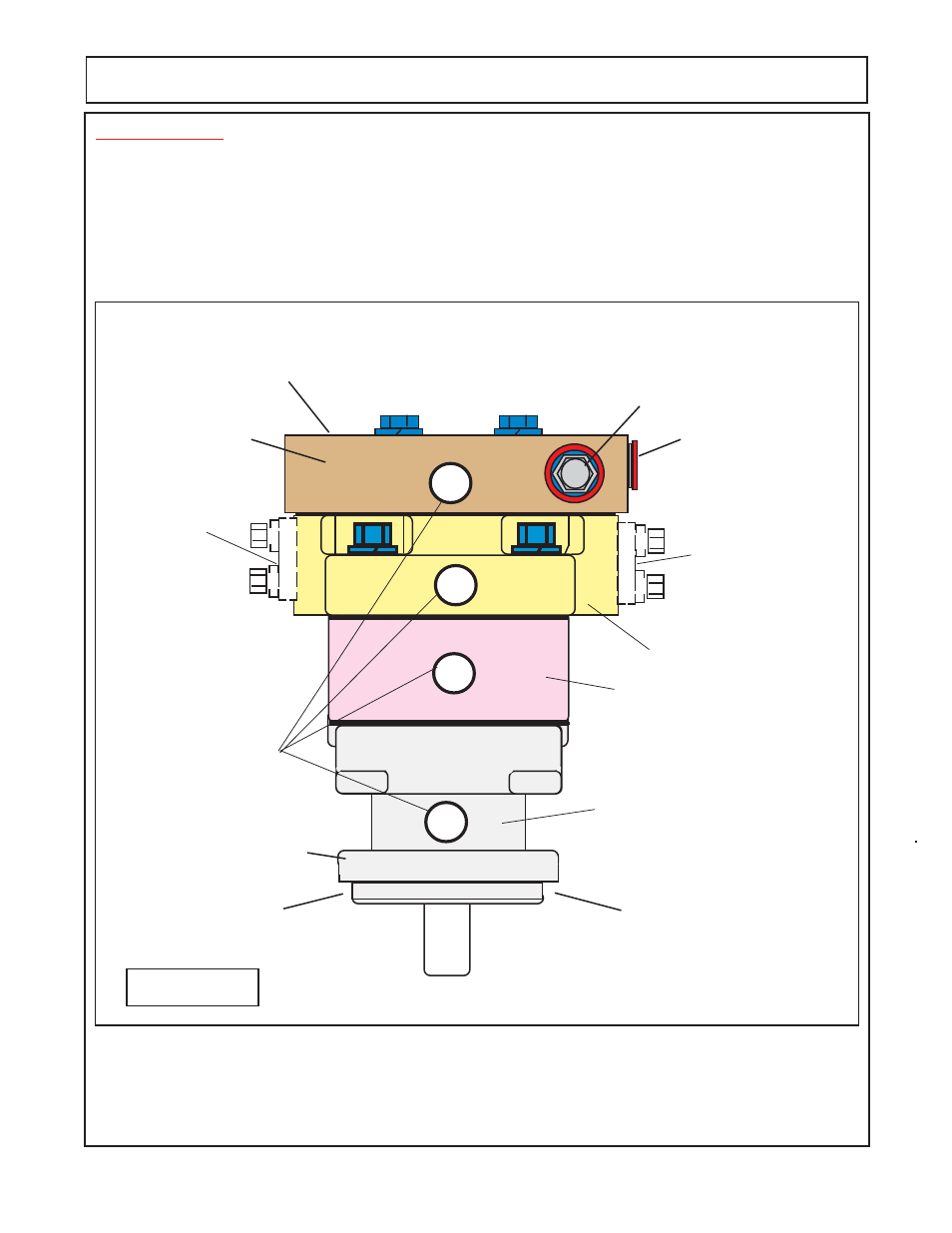
IMPORTANT !
(CENTER MOTOR)
Mark all Sections of Motor with a Number (or) Symbols that will serve as a guide to all sections
being re-installed the same way they were removed. Example: if the numbers (marks) do not line up
(1, 2, 3 & 4 ) as they were marked, the Motor is not being assembled correctly. Check this all through
the assembly process. The Motor will rotate in the wrong direction if connected wrong. NOTE: The
manifold block will always mount with the relief valve on the same side as the pressure inlet. If installed
wrong the motor will not function properly because the relief valve will not work.
Figure 13
1" Split Flange
Pressure
(inlet) Side
Shaft End Cover
Gear Housing
Port End Cover
12345678
12345678
12345678
12345678
12345678
12345678
12345678
12345678
12345678
12345678
12345678
12345678
12345678
12345678
1
3
2
Service Technician
Makes Alignment Marks
Here
Plug
Relief Valve (3000 psi)
Manifold Block
(Center Motor)
4 Bolt Mounting Flange
Front of Motor & Mower Shown
LH Side of
Motor & Mower
RH Side of
Motor & Mower
Check Valve Cartridge
(Back Side Not Seen)
Center Motor Only
4
1" Split Flange
Return
(Outlet) Side