Wing lift & fold cylinder repair – Alamo HYDRO 15 User Manual
Page 82
HYDRO 15 (Service Manual) 10/06
© 2006
Alamo Industrial
Section 5 - 8
WING LIFT & FOLD CYLINDER REPAIR
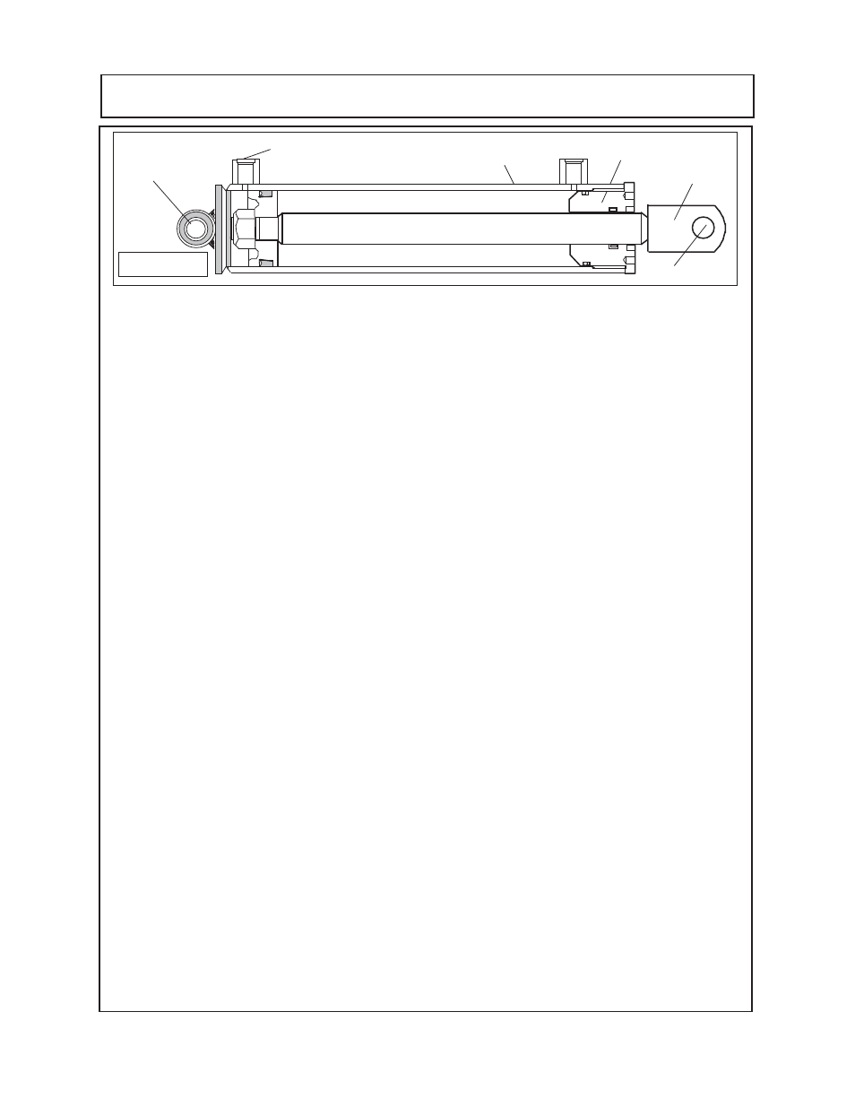
Cylinder Removal: (LH or RH Wing Cylinder)
1.
Make Certain Wings are in the lowered position before disconnection any component. Make
certain tractor is securely parked with brakes set. Make certain tractor engine is in off position and
key secured to prevent starting. It is recommended mower be disconnected from tractor or battery
cable be removed from battery while repairs are being made.
2.
Make certain that all hydraulic pressure has been released from lines after wings and axles
have been completely lowered. This may require the tractor hydraulic controls and / or remote
control valve be worked to release hydraulic pressure.
NEVER disconnect any cylinder hydraulic
hose's or fittings if all
mower components (wings and deck) are not resting in the completely
lowered to the ground position.
3.
Remove the cylinder mounting pins
(figure 1 item 1)
, this allows the cylinder to be raised
upward off the wing lug and outward from the cylinder mount of the winch stand.
4.
Before disconnecting the base end hose
(figure 1 item 2)
form the wing cylinder put a drain
pan under the hose connection at the base end of the cylinder. Begin to loosen the hose slowly,
If any hydraulic pressure is in the hose STOP and reread step 2 above. If no Hydraulic pressure,
continue removing the hose from the base end of the cylinder while keeping the hose and cylinder
over the drain pan. When hoseis removed hold cylinder over drain pan until oil has drained from
cylinder. Install a cap onto the cylinder hose to seal it.
Cylinder Dis-Assembly: (LH or RH Wing Cylinder)
1.
Clamp cylinder to work bench
(DO NOT over tighten clamp and bend or distort the shape of
the barrel)
only tight enough to hold cylinder. Place a drain pan under cylinder head to catch any
oil that may leak out.
2.
Pull the Cylinder Rod Clevis Weldment
(figure 2 item 3)
outward at least 3 inches, This will allow
the Cylinder Head
(figure 2 item 4)
to be unscrewed from Barrel
(figure 2 item 5)
using a
commercially available two point spanner wrench
(figure 13)
. The cylinder head will screw counter
clockwise out until it is away from the cylinder barrel. Hold the Cyl rod
(figure 2 item 3)
as straight
as possible when cylinder head is unscrewed.Keep drain pan under open end of barrel to catch
oil that may drain from barrel.
3.
Pull the Cylinder Rod Clevis Weldment
(figure 2 item 3)
outward, it will pull the piston out of the
barrel
(figure 2 item 6).
When pulling the rod and piston out do it slowly, the amount of resistance
should be about the same all the way out, if you encounter a spot where the piston pulls easier
than others make a mark on the OD of the barrel approx where the piston is in the barrel. These
loose places may indicate a worn are that will need to be checked later. Pull the rod out slowly
holding the rod as straight as possible until the piston
(figure 2 item 6)
and cylinder rod weldment
pulls completely out of barrel
(figure 2 item 5)
. Be careful not to bump the threads on the cylinder
head or damage them.
4.
Clamp cylinder rod clevis weldment in a vice (
figure 3)
on the clevis end as shown. Clamp the
rod with the mounting pin hole upward as shown
(See Rod Clevis Weldment figure 3)
, if the clevis
is clamped with the hole the other way, the clevis could be bent together and cause the clevis to
be deformed.
1
2
3
1
5
4
12
12
12
12
12
12
12
12
12
12
12
12
12
12
12
12
12
12
1234567890123456789012345678901212345678901234567890123
1234567890123456789012345678901212345678901234567890123
1234567890123456789012345678901212345678901234567890123
1234567
1234567
1234567
Figure 1