Standard axle lift cylinder repair – Alamo HYDRO 15 User Manual
Page 95
Section 5 - 21
HYDRO 15 (Service Manual) 10/06
© 2006
Alamo Industrial
STANDARD AXLE LIFT CYLINDER REPAIR
8.
Install the new nylon thread protector
(figure 6 item 2)
into the cylinder rod clevis
(figure 6 item
3)
, Make certain the nylon thread protector is laying flat in the bottom of the threaded hole in the
clevis. Insert the setscrew
(figure 6 item 2)
into the clevis
(figure 6 item 3)
. Tighten the clevis
setscrew to
20 ft. lbs
(base on 3/8” setscrew).
9.
Coat the cylinder base barrel seals
(figure 6 & 9 item 8)
with coat of hydraulic oil. Install the
cylinder base end into the barrel
(see figure 9)
. If plastic plug is installed in base end as shown
(see
figure 9)
it will allow the insertion of the base end into the barrel if plug is removed. Make certain
that the ports on the base end are aligned with thew cylinder head as shown
(see figure 9 item 8
& 9)
, the ports
must be aligned
this way.
10
Install cylinder tie-rods
(figure 9 item 6 & 7)
, make certain that the hex nuts that were left on
the tie-rod is loose. Insert the tie- rods
(qty 4)
and the hex nuts
(qty 8)
onto the tie-rods. The hex
nuts must be screwed on at the same rate and on each end, try to keep the same amount of threads
sticking out the nuts on both ends of the tie-rods. Snug the nuts down an all 4 tie rod evenly and
alternating as to keep the same amount of pressure evenly. Torque the tie-Rod nuts to
80 ft. lbs
(based on a 1/2” tie-rod).
11.
Install the vent plug into the cylinder head port
(figure 9 item 9)
at the Rod End of cylinder.
Install the hydraulic elbow adapter to the base end of cylinder
(figure 9 item 8)
. Note; plug the open
end of the hydraulic adapter until time to connect the hose to it.
1234
1234
1234
1234
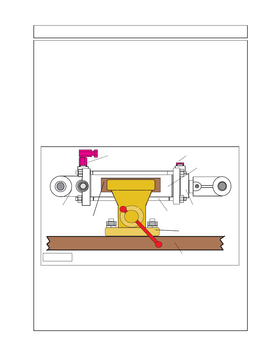
Figure 9
Wood or other soft
material
Bench Vise
Work Bench
9
(cyl head, clevis, cyl
rod & piston asy).
5
8
12
12
12
12
1234
1234
1234
1234
12
12
12
12
12
6 & 7
123
123
123
123
123
123
12
12
12
12
12
12
1234
1234
1234
Vent Plug
Hydraulic Elbow
Adapter
12.
Install the cylinder onto mower, Mount the cylinder with the base end
(figure 9 item 8)
to the
deck lug. Mount the cylinder head / rod end
(figure 9 item 9)
of the cylinder to the axle lug. When
first using the rebuilt and/or new cylinder it is not unusual for a light amount of oil to be pushed
out of the vent. The amount is the amount that was used to oil components during assembly.
If excessive amount leaks through the vent, cylinder is not functioning properly. Recheck the
assembly steps for possible assembly error.