Wing lift & fold cylinder repair, 6 & 6c 7 – Alamo HYDRO 15 User Manual
Page 87
Section 5 - 13
HYDRO 15 (Service Manual) 10/06
© 2006
Alamo Industrial
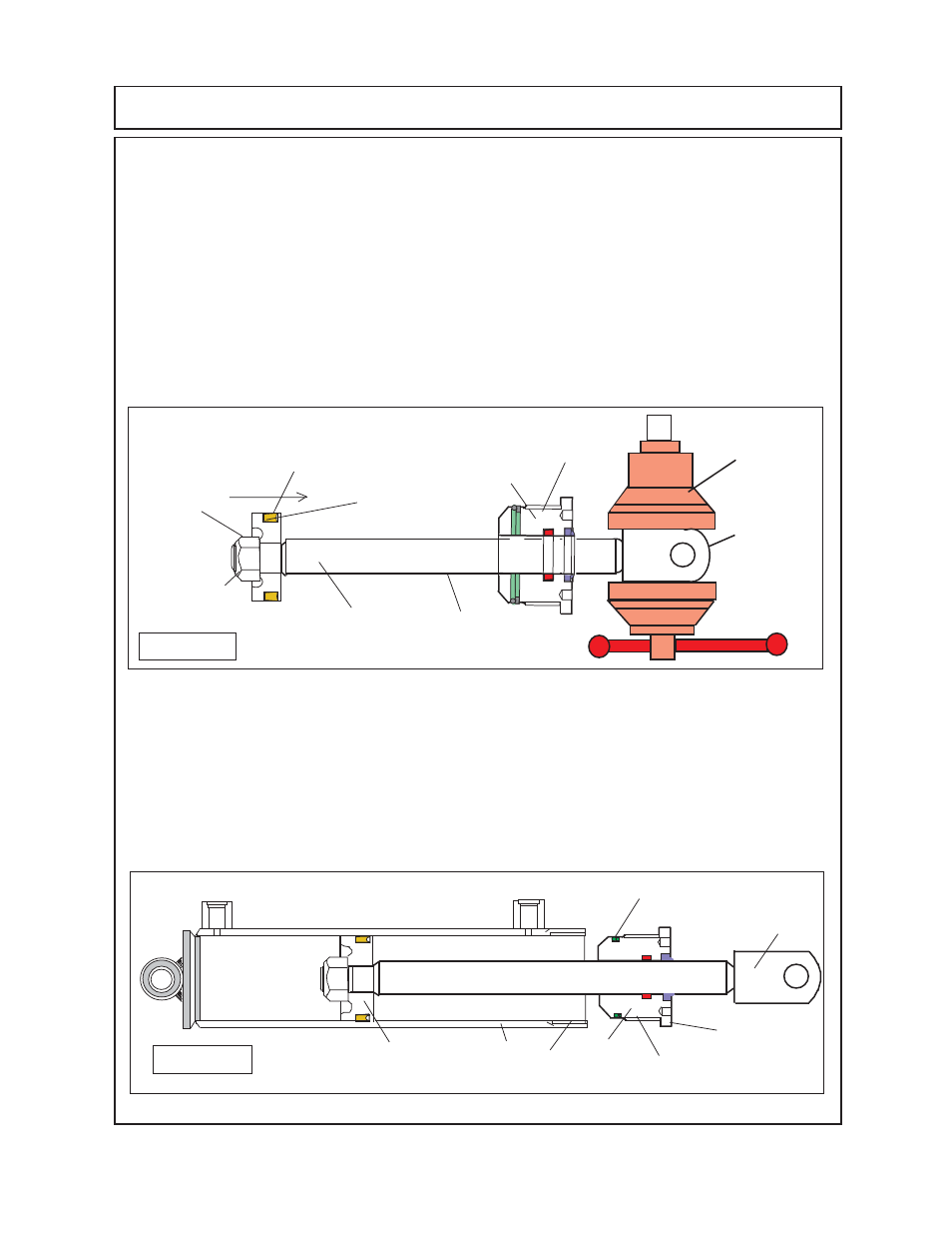
11.
Coat the piston
(figure 10 item 6)
and ID of the barrel
(figure 11 item 5)
with light coat of hydraulic
oil. Clamp the barrel down just enough to hold it being careful not to over tighten it, or the barrel
could be distorted. Holding the cylinder rod straight slowly slide the piston into the barrel, be careful
at the front of the barrel when sliding piston across the threads in the barrel
(figure 11 Item 5
Threads)
so as not to damage U-Cup seal on piston
(figure 11 item 6)
. When piston is being slid
into barrel do it slowly feeling the resistance, the resistance should remain about the same all the
way in, if not recheck barrel for wear. Continued to slide piston in holding rod as straight as possible
until it is in barrel approx 10 to 12 inches making certain the cylinder head
(figure 11
item 4)
is not
inside barrel.
WING LIFT & FOLD CYLINDER REPAIR
8.
Install the U-Cup Seal
(figure 10 item 6C)
onto Piston
(figure 10 item 6)
. The U-Cup Piston seal
is a directional seal and is designed to be used as a single action cylinder. The U-Cup seal should
be installed so the U-Cup side of seal is toward the pressure side of the piston which is the rod
side on this cylinder.
9.
The cylinder rod weldment is clamped into vice as shown
(figure 10 item 3)
Clamp the rod with
the mounting pin hole upward as shown
(See Rod Clevis Weldment figure 10 item 3)
, if the clevis
is clamped with the hole the other way, the clevis could be bent together and cause the clevis to
be deformed.
10.
Install the new Piston retaining locknut
(figure 10 item 7)
onto the cylinder rod. (Note it is not
recommended that old locknut be reused). Before tightening the locknut down make certain that
piston is seated onto cylinder rod completely, this can be done by visually inspecting back side of
piston against shoulder of cylinder rod. Torque Piston Locknut
350 to 400 ft lbs.
12
12
12
12
12
12
12
12
12
12
12
12
12
12
12
12
12
12
1234567890123456789012345678901212345678901234567
1234567890123456789012345678901212345678901234567
1234567890123456789012345678901212345678901234567
1234567
1234567
1234567
123456
123456
1234567
4
3
Figure 11
5
Cyl Head
6
Cyl Head
Threads
Barrel
Threads
O-Ring & Back-Up Washer Seal
3
Figure 10
Vise
Cyl Rod
Clevis
Weldment
12345
12345
12345
12345
12345
Cyl Rod & Clevis
Weldment
Cyl Head
4
1234567
1234567
Piston w/ U-Cup
Seal Installed
6 & 6C
7
Piston
Locknut