Motor service & repair, Figure 39 figure 41, Figure 38 figure 40 – Alamo HYDRO 15 User Manual
Page 59
Section 3 - 21
HYDRO 15 (Service Manual) 09/06
© 2006
Alamo Industrial
MOTOR SERVICE & REPAIR
16.
Lightly coat the gear journals with grease. When
placing the Port end housing
(figure 42)
over gears,
use
caution
so you don't hit and damage gear shaft journals.
Place the bearing carrier onto gear shaft journals of the
drive and the driven gears.
Be sure to align the dowel pin
holes
over with dowel pins. When the parts are parallel
squeeze them together or alternately tap over each dowel
until the parts are together.
DO NOT
use excessive force to
put housing together, if light taping won't do it something
is wrong
(figure 42).
MAKING CERTAIN
the marks made
to keep the components in the same orientation when re-
assembled are aligned
(figure 13 & 14)
.
17.
Thread the bolts & lockwashers in through shaft end
cover of gear housing until threads are started into bearing
housing. Alternately tighten the bolts in increments that
will make the three components pull down evenly
(figure
42 & 43).
Torque the bolts in increments until the bolts
(qty
4)
are torqued to
200 ft. lbs.
18
Install the manifold block to top of the motor. The
manifold block on the LH and RH wing are the same and will
mount with the return line toward the front of the mower. The
manifold block for the center motor will only work with the
center motor and is installed with the relief cartridge toward
the front on the LH side. The Wing motors use two large O-
Rings and one small O-Ring on each manifold, The center
motor uses two large O-Rings to install manifold block.
When tightening the four retaining bolts, they MUST be
tightened evenly in increments so block remains un-
distorted.
DO NOT over tighten any one bolt
it will distort
aluminum manifold block. Torque the 5/16" Gr 5 bolts to 16
to 20 ft. lbs.
(figure 45. 46 & 47).
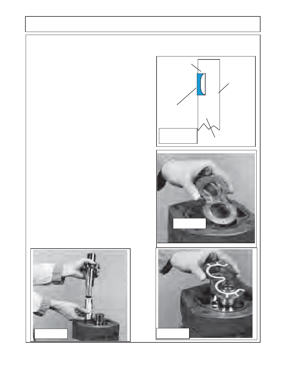
Figure 39
Figure 41
Gear Side
Smooth
Channel Seal
Side Grooved
Smooth Side
Channel Seal
Outward
1234567
1234567
1234567
1234567
1234567
1234567
1234567
1234567
1234567
1234567
1234567
1234567
1234567
1234567
1234567
1234567
1234567
1234567
1234567
1234567
1234567
1234567
1234567
1234567
1234567
1234567
1234567
1234567
1234567
1234
1234
1234
1234
1234
1234
1234
1234
1234
1234
1234
1234
1234
1234
1234
1234
1234
1234
1234
1234
1234
1234
12345
12345
12345
12345
12345
12345
1234
1234
1234
1234
1234
1234
1234
1234
1234
1234
1234
1234
1234
1234
1234
Thrust Plate
Figure 38
Figure 40
15.
Slip the second thrust plate with the channel seal installed
(figure 41)
over the gear journals and into the
down over the gear shaft journals
(figure 41)
. The flat side of the seal should face down with the relief groove of
thrust plate facing the gears. Check the gear housing gasket seal
(figure 15)
is still in place on gear housing
(figure 36).