Pump service & repair, Figure 22, Figure 23 – Alamo HYDRO 15 User Manual
Page 29
Section 2 - 13
HYDRO 15 (Service Manual) 09/06
© 2006
Alamo Industrial
Figure 19
Figure 20
Figure 21
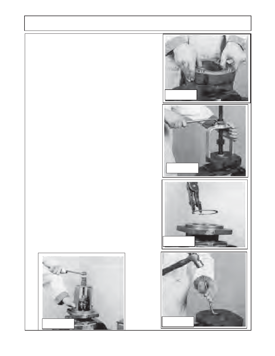
9.
Lift or pry off the first section of gear housing
(figure 10 item
12).
Be careful not to damage machined surfaces
(figure 19).
Inspect the gear housing
(See wear tolerance
chart for pump
and motors in this section).
for wear and / or damage.
10.
Inspect all of the bushings for scoring or discoloration
(figure
10 item 6 qty 8)
in the port end cap, bearing carrier (both sides)
and the shaft end cover. If they need to be replaced use a
bushing puller as shown
(figure 4 recommended tools list)
.
Remove the bushings with care not to damage housings
(figure
20).
11.
Remove shaft end cover
(figure 10 item 4)
from vice and turn
it 180° over and re-insert it into vice. Using snap ring pliers
remove the snap ring
(figure 10 item 1)
as shown
(figure 21).
12.
Remove the shaft bearing
(figure 10 item 2)
using a bearing
puller
(figure 22).
Make certain to use the correct size bearing
puller and that puller is inserted straight.
13.
Remove shaft end cover
(figure 10 item 4)
from vice and turn
it 180° over and re-insert it into vice. Remove the double lip seal
by inserting the special seal removal tool
(see figure 6 recom-
mended tools).
Make note of which way seal is removed. Inspect
the shaft end cover seal seat area
(figure 23).
14.
Inspect all the components that have been removed (
review
steps 1 through 13).
There are 4 gasket seals (
figure 10 item 10)
that are installed, one on each side of the gear housing. Make
certain the gasket seal have been removed and the gasket
grooves are clean. Wash and clean all the components,
DO NOT
use any material that will leave lint on components, it 's best to
air dry the components. Use extreme caution when cleaning
gear sets, DO NOT use any abrasive materials at all and
DO
NOT
bang the gears together. Keep the gears in the same sets
as they were remove as they are a matched set and must
remain as a set.
(See next two pages for wear identification).
Figure 22
PUMP SERVICE & REPAIR
Figure 23