Motor service & repair, Figure 12, Figure 11 – Alamo HYDRO 15 User Manual
Page 47: Figure 10, Hydraulic connections
Section 3 - 9
HYDRO 15 (Service Manual) 09/06
© 2006
Alamo Industrial
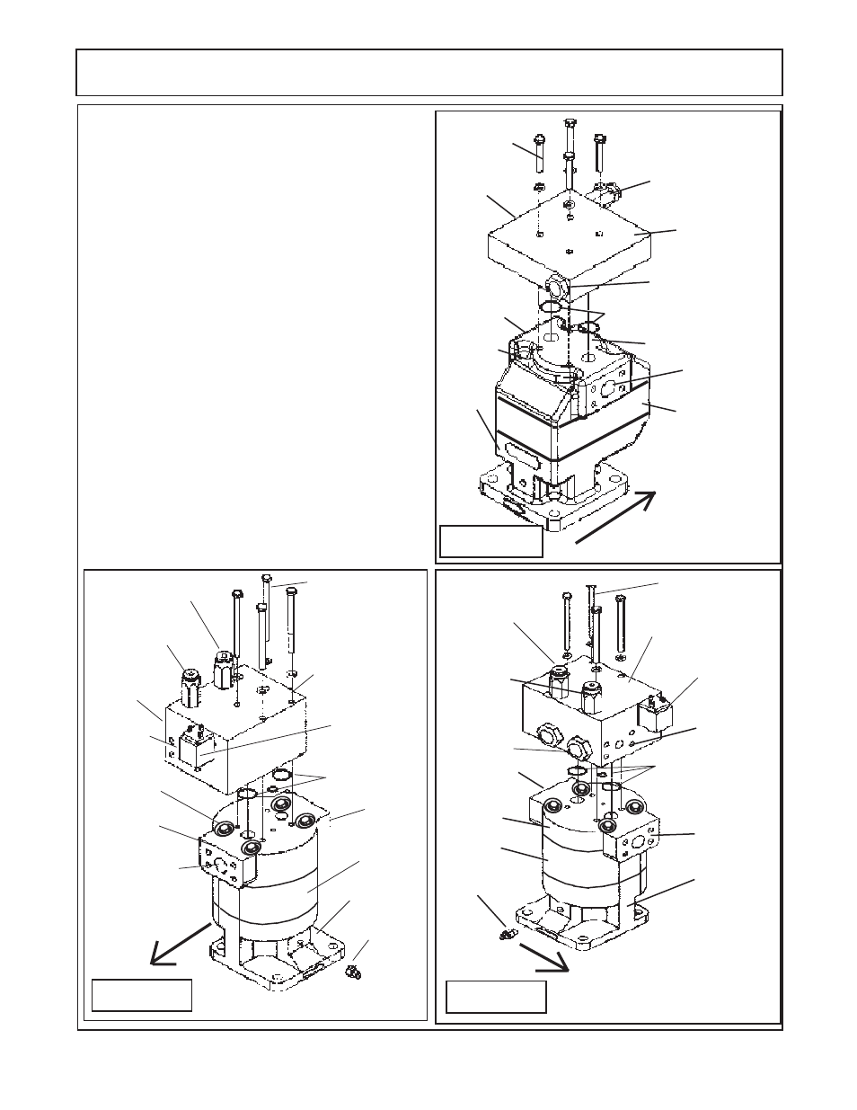
MOTOR SERVICE & REPAIR
Manifold Block
Mnt Bolts
Manifold Block
(LH Wing Motor)
Solenoid
Stem
& Coil
Relief Cartridge
(2000 psi)
Relief Cartridge
(800 psi)
Logic
Cartridge
Manifold Block
O-Rings
Plugged
Port
Pressure
Port (Inlet)
Return
Port (Outlet)
Port End
Cover
Gear
Housing
Shaft End
Cover
Case
Drain
Fitting
FRONT OF MOWER
LH WING MOTOR
Figure 12
RH WING MOTOR
Manifold Block
Mnt Bolts
Relief Cartridge
(800 psi)
Relief Cartridge
(2000 psi)
Manifold Block
(RH Wing Motor)
Manifold Block
O-Rings
Solenoid
Stem
& Coil
Motor Asy
Bolts (4)
Shaft End
Cover
Gear
Housing
Port End
Cover
Logic
Cartridge
Case
Drain
Fitting
Pressure
Port (Inlet)
Plugged
Port
Return
Port (Outlet)
FRONT OF
MOWER
Figure 11
Gear
Housing
Shaft
End
Cover
Port End Cover
Cartridge Check
Valve
Manifold Block
(Center Motor)
Relief Cartridge
(3000 psi)
Pressure
Port (Inlet)
Return
Port (Outlet)
FRONT
OF
MOWER
Figure 10
Manifold Block
Mnt Bolts
Manifold Block O-Rings
Motor Asy
Bolts (4)
CENTER MOTOR
LH Wing:
The LH wing motor is basically the same as the
R H wing motor with the exception of the Port end cap
is installed different
(figure 12)
. The wing motor the
four assembly bolts are in a machined hole under the
manifold block. The manifold block will need to be
removed to see them. LH Wing motor is assembled
to turn in CCW rotation which should be marked on
the motor mounting flange from the factory. The
rotation is determined by standing on the deck
behind the motor
facing forward. On the wing
motor the four assembly bolts are in a machined hole
under the manifold block. Make certain which motor
is being serviced,
Hydraulic Connections:
Center Motor
The hydraulic connections are connected to the
Motor for the inlet and outlet side with a 1 inch split
flange connection
(figure 10).
RH & LH Wing Motor
The hydraulic connection for the Inlet is con-
nected to the motor with a 1 inch split flange
connection, The outlet connection is on the manifold
block with a 1 inch split flange connection
(figure 11
& 12).
Plug
(not seen)