Standard axle lift cylinder repair – Alamo HYDRO 15 User Manual
Page 90
HYDRO 15 (Service Manual) 10/06
© 2006
Alamo Industrial
Section 5 - 16
STANDARD AXLE LIFT CYLINDER REPAIR
Cylinder Removal: ( Axle Lift Cylinder, Standard)
1.
Make Certain
axles are in the lowered position before disconnection any component
.
Make
certain tractor is securely parked with brakes set
.
Make certain
tractor engine is in off position
and
key secured to prevent starting
. It is recommended mower be disconnected from tractor or
battery cable be removed from battery while repairs are being made.
Front and rear of mower must
be securely supported on strong jackstands before hydraulic lines or cylinder mounting pins of the
axle hydraulic assembly are disconnected.
2.
Make certain
that all hydraulic pressure has been released from lines after wings and axles
have been completely lowered. This may require the tractor hydraulic controls and / or remote
control valve be worked to release hydraulic pressure.
NEVER disconnect any cylinder hydraulic
hose's or fittings if all
mower components (wings and deck) are not resting in the completely
lowered to the ground position or supported on jackstand position.
3.
Do not remove cylinder pressure hose before the cylinder is dismounted from deck. Remove
the cylinder mounting pins
(figure 1 item 1)
, this allows the cylinder to be raised upward off the deck
mounting lug and the axle lug. Place a drain pan under the pressure hose to catch the hydraulic
oil when hose is disconnected. Drain cylinder and hose into drain pan. Plug the pressure hose to
keep contamination out of it.
4.
Plug all openings in cylinder before cleaning the cylinder. Remove the Vent Plug
(figure 1 item
10)
and insert a plug
(plastic plugs will work)
. Base end of cylinder
(figure 1 item 8)
will have two
ports, Pressure hose port
(figure 1 item 11)
and second plugged port on side
(figure 1 item 12)
which
should still be in cylinder base.
1234567
1234567
1234567
1234567
1234567
1234567
1234567
1234
1234
1234
1234
1234
1234
123456789
123456789
123456789
123456789
123456789
123456789
123456789
123456789
123456789
123456789
123456789
123456789
123456789
123456789
123456789
12
12
12345678901234
12345678901234
12345678901234
12345678901234
12345678901234
12345678901234
12345678901234567890123456789012123456789012345678
12345678901234567890123456789012123456789012345678
12345678
12345678
12345678
1234567
1234567
12
12
12
12
12
12
12
123456
123456
123456
123456
123456
123456
123456
123
123
123
12
12
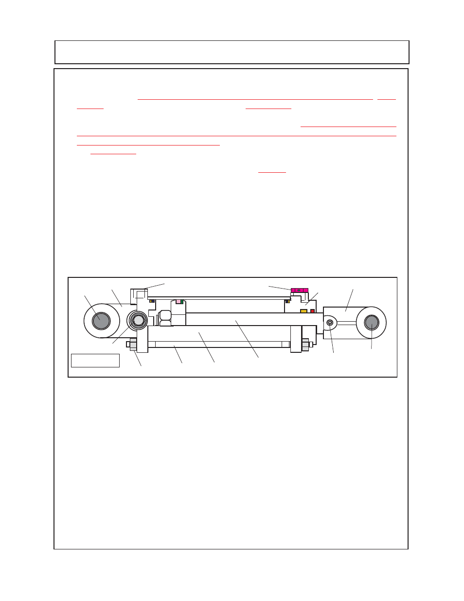
Figure 1
1
1
2
3
4
6
5
7
9
8
10
11
12
Cylinder Dis-Assembly: (Axle Lift Cylinder, Standard)
1.
This is a Tie-Rod construction type cylinder, the four tie-rods
(figure 1 item 6)
and the 8 hex
nuts
(figure 1 item 7)
bolt the cylinder together. When these tie-rods are unbolted the cylinder will
come apart with minimum effort but
DO NOT
unbolt tie-rods until later.
It is recommended
that the
barrel of the cylinder be marked as to which end isthe cylinder rod end and which is the cylinder
base clevis end.
2.
Place the cylinder in a bench vise
(figure 2)
, use pieces of wood or other soft material between
vise jaws and cylinder barrel.
DO NOT
over tighten vise and distort the shape of the barrel, vise
only needs to be tightened enough to hold cylinder.
3.
Place drain pans under cylinder to catch hydraulic oil that may still be in cylinder (
figure 2 Drain
Pans)
. Using ratchet w/ sockets or boxed end wrenches
(repair technicians choice)
remove the
tie-rod hex nuts
(figure 2 item 7).
The tie-rods have a hex nut on each end
(figure 2 item 7)
, not
all the hex nuts will screw off on the same side. The hex nut with the least amount of resistance
is going to screw off. This is OK as the tie-rods can be pulled out from either direction.
4.
When a hex nut has been removed from each tie-rod (it will not matter which end of tie-rod)
pull the tie rods out from the cylinder base and cylinder head
(figure 2 item 6).
There are a total
of 4 tie-rods that will need to be removed
(see figure 3)
.
.