Pump service & repair, Figure 27 figure 26, Figure 25 pump assembly – Alamo HYDRO 15 User Manual
Page 33
Section 2 - 17
HYDRO 15 (Service Manual) 09/06
© 2006
Alamo Industrial
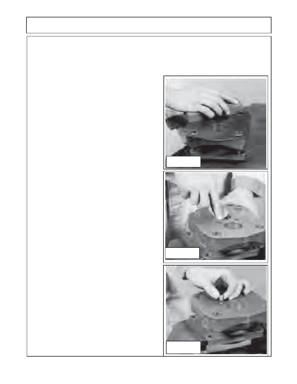
Figure 27
Figure 26
PUMP SERVICE & REPAIR
before continuing installation of other components. Re-
place the parts with machined surfaces if required. Check
components for wear or damage now before continuing.
2.
If the bushings (figure 10 item 6) were removed and new
ones need to be replaced. Inspect the holes where
the
bushing will be pressed in. If there are burrs or rough edges
at the tops of the holes they can be de-burred by using your
finger and emory cloth. Keep the emory cloth on an angle
and only around the top of the bore
(figure 26).
Do this to each
hole for the bushing that are to be replaced
. IMPORTANT !
Bushing must be pressed in with an arbor press
DO NOT
drive them in with a hammer.
3.
Insert the shaft end cover in the vise with the machined
surface up
(figure 27)
. Examine the plug in the surfaced area.
It is NOT required to remove this plug
un-less the shaft end
housing is being replaced. This pump (PGP/PGM 365
Series) has one plug and it is installed on determines the
direction of travel of the pump,
DO NOT
change the location
of this plug un-less you want to change travel direction.
If
plug is changed by error
the pump will be damaged when
engaged, it will most likely blow the shaft seal out of it and
it may damage other components in the mowers hydraulic
system. This plugged is change by using a screw driver if
need be.
4.
If new plugs are to be installed, coat the threads of the
plug with locktite™ thread sealant. If new plugs have been
installed, they need to be screwed in tightly. Stake the plug
with a prick punch at both ends of the screw drive slot and
around the edges. Peen the edge of the hole 1/32" to 1/16"
with a 1-1/2" dia steel ball (a 1-1/2" ball peen ball end of a
hammer can be used for this
(figure 28)
, when striking ball
peen hammer flat end put a piece of cloth over it to prevent
chips from flying off of hammer .
DO NOT
use hammer direct
to hit plugs
5.
Note
: Steps 5, 6, 7 & 8 apply to Shaft End Cover
(figure
10 item 4),
Bearing Carrier
(figure 10 item 13)
and Port End
Cover
(figure 10 item 17)
Any bushing removed from the shaft
end cover, port end cover or bearing end cover should be
assembled in the drive bores with the grooves to the top of
unit
(12 O'clock)
. Assemble the bushings in the driven bores
with the groove to the bottom of the unit
(6 O'clock)
. The
Grooves refer to the bearing seam
(figure 29).
Figure 25
Pump Assembly:
1.
Check all the machined surfaces on all pump components to make certain they are level and free of
scratches. Minor scratches and slight un-level conditions may be fixed by using a Medium Grit Carborundurn
Stone. This must be done equal all the way across the face of the machine surface to keep it level
(figure 25).
ALL part must be cleaned and dried
if stone is used it
. If deep scratches or excessively un-level the section
will need to be replaced, so make certain this is checked