2 mix-down signal path with processing inserted, Input channel & inserts – Sony OXF-R3 User Manual
Page 64
4-4
Chapter 4
Signal Paths
Chapter 4 Signal Paths
4-2 Stereo Mix-down Signal Path With Processing Inserted
For each channel, select {MIC} , {M/T} , or {LINE} as the mix-down source,
depending on the situation. All input types may be cross-patched as
desired via the LCD screens above the Channels areas.
(Refer to Chapter 5, Control Screens for details).
As described previously, the Input Channel & Inserts section allows the
setting up of processing functions in any order. The example
configuration shown is a good starting point in a mix-down situation.
‘MULTI’ should not be selected in any window for multitrack mix-down. ‘MULTI’
is used in the channel path to create an in-line channel, described later in this
chapter.
Note:
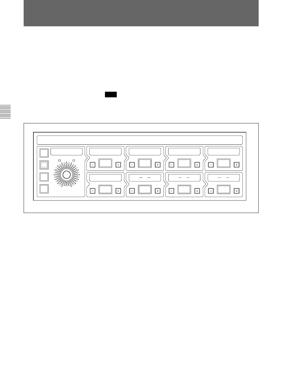
Mix-down channel path - example configuration
The fire-up default sets all channel outputs routed to the Main Output Bus
via the {MAIN} button on the Routing panel. To feed the Main bus directly,
make sure {MAIN} is selected on. Alternatively, channel outputs can be
routed to Super Send Groups (SSGs) to group a selection of channels
together.
To accomplish this, de-select {MAIN} and select an SSG at the Routing
Panel. The output of the SSG can itself be routed directly to the Main
Output Bus by selecting its {MAIN} button in the Multi-Format & Super
Send Groups section, in the centre section.
Each SSG has its own knob for level control. Alternatively, on the Select
To Faders panel in the SEL section, select SSGs 1-8 to set faders in the
centre section to control SSG levels. The fire-up gain setting for SSGs is
unity.
INPUT CHANNEL & INSERTS
MIC
IN
IN
IN
IN
IN
IN
GAIN
M/T
LINE
ø
– 20 dB
F I L T E R
D Y N
E Q
I N S E R T
D E L A Y
7
6
IN
IN
8
4-2 Mix-down Signal Path With Processing
Inserted