1 the basic (default) signal path – Sony OXF-R3 User Manual
Page 62
4-2
Chapter 4
Signal Paths
Chapter 4 Signal Paths
4-1 The Basic (Default) Signal Path
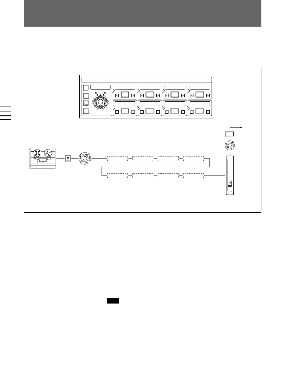
When the OXF-R3 is switched on, the system sets a default configuration
as described in this section.
Signal paths are built using the controls on the Input Channel & Inserts
section of the Input and Equaliser Module. Section 6-2-5 in Chapter 6
provides details of these controls.
In the default configuration shown, the M/T source button is selected and
its signal feeds the multitrack phase reverse switch and gain control. The
windows labelled 1 to 8 are available to insert processing elements such as
EQ and dynamics but, in this default configuration, none are selected.
From the phase reverse switch and input gain stage, the signal is passed
directly on to the channel fader, through the channel pan and on to the
MAIN L/R output bus.
The MIC, LINE and M/T inputs each have their own individual phase switches
and gain control stages.
Default signal path
Note:
4-1 The Basic (Default) Signal Path
INPUT CHANNEL & INSERTS
0dB
GAIN
– 1 –
– 2 –
– 6 –
– 3 –
– 4 –
– 1 –
– 2 –
– 3 –
– 4 –
– 8 –
– 7 –
– 5 –
– 6 –
– 8 –
– 7 –
– 5 –
ø
M/T
MIC
LINE
IN
IN
IN
IN
IN
IN
IN
IN
CHANNEL
FADER
10
10
5
5
5
5
10
10
20
20
30
30
40
40
60
70
∞
∞
0
0
C H O U T P U T
L & R
PAN
MAIN
C H I N P U T
G A I N