2 channel screens – Sony OXF-R3 User Manual
Page 154
5-40
Chapter 5
Control Screens
Chapter 5 Control Screens
5-2 Channel Screens
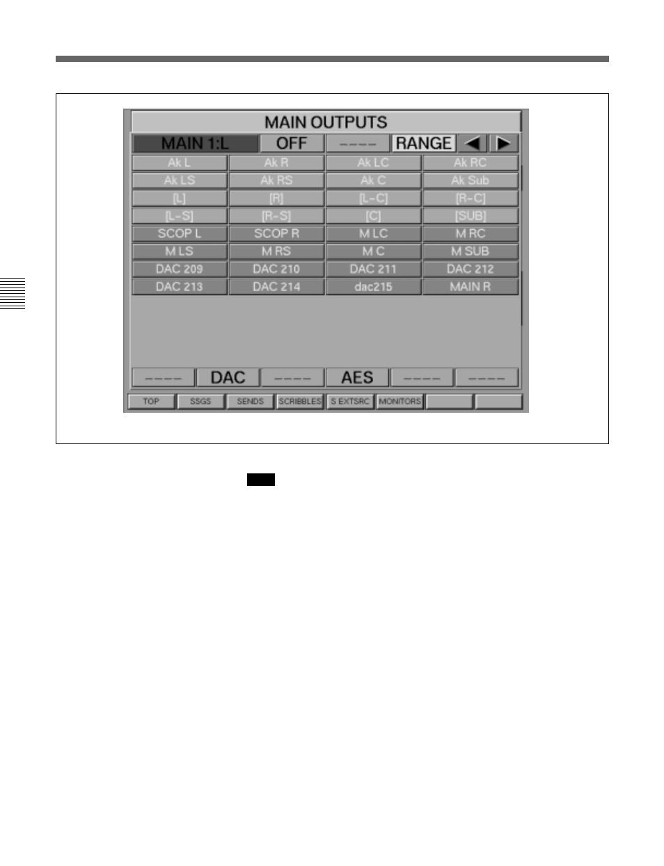
MASTER GUI - MAIN OUTPUT BUS output pop-up
Figure A
Whilst the following describes selecting destinations and inserts for the MAIN
BUS, the methods of operation apply to all pages related to the MASTER GUI.
General
The clickable fields in the Main Output GUI are laid out in the form of a
set of Surround LS. The upper section contains a single set of Inserts
which affect all four outputs.
OUTPUT FORMAT – MAIN OUTPUT 1 upper section
The 8 fields labelled { L } , { L-S } , etc. allow the selection of I/O
destinations for the Main Output 1. Eight fields are displayed in the
illustration, but the number displayed depends upon the current format for
the Main Output Bus. Click on any of these fields to display the pop-up as
shown in Figure A, which lists analogue outputs. Click on one of them to
select it or click on AES for the list of digital destinations.
OUTPUT FORMAT – MAIN OUTPUT 1 lower left
The 4 buttons labelled { 8 }, { 6 }, { 4 }, and { 2 } inter-cancel allowing the
setting of the format for the output, 7.1, 5.1, LCRS or Stereo respectively.
A Fold-down Matrix derives signals for formats with fewer outputs than
the Main Bus.
WORD LENGTH – MAIN OUTPUT 1 lower middle left
This field is displaying ‘ANALOGUE’ in the illustration, since analogue
Note: