Input channel, Ch input ch output – Sony OXF-R3 User Manual
Page 196
6-34
Chapter 6
Technical Descriptions
Chapter 6 Technical Descriptions
6-2 Channels Section Panels
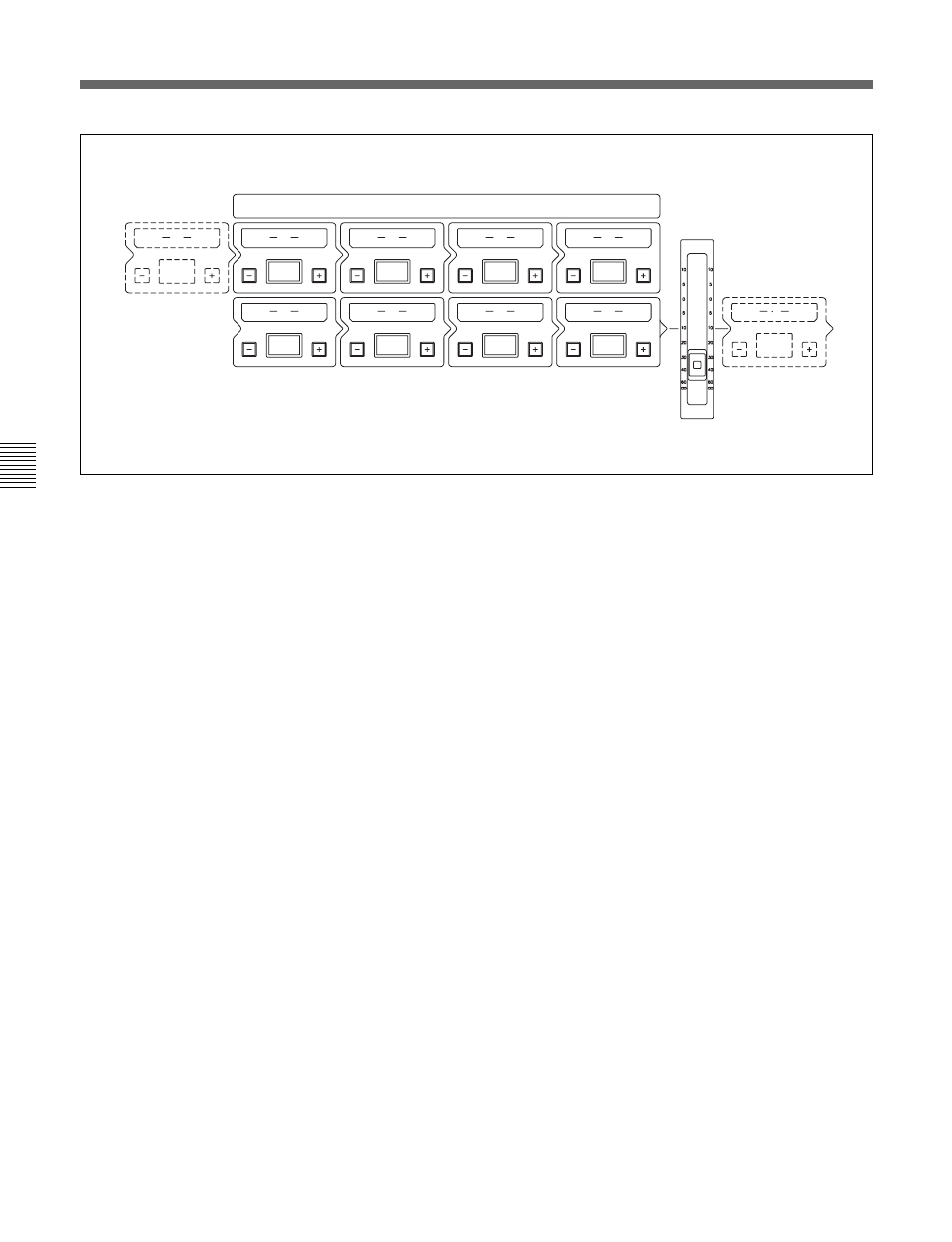
Source point options for Sends
CH INPUT
CH OUTPUT
INPUT CHANNEL
INPUT CHANNEL & INSERTS
0
1
5
IN
IN
IN
2
6
IN
IN
3
7
IN
IN
4
8
9
CHANNEL
FADER
IN
IN
IN
Input channel source points for the Sends in detail
This diagram illustrates the channel path as laid out at the Input Channel &
Inserts panel. Source points may be taken from after any of the processing
block windows, 1-8, as well as before the first block, and after the last one,
post the channel fader. The diagram shows the extra source points as
imaginary windows within the channel path. The Source point pre
window -1- will be displayed as CH INPUT, which takes a totally clean
signal from post the input gain stage. The Source post fader is labelled
C OUTPUT as displayed on the 8 character display in the SOURCE
selector area.
M/T Send Fader source point for Sends
A further option as a source point for Sends, is the signal post the M/T
Send Fader. This is indicated by MT SEND in the Source display
(see page 6-37 for more details).