13-4 stem monitor switching, 13 multi-stem set-up, 12 3 4 rows remotes – Sony OXF-R3 User Manual
Page 108: Stem monitor switch mapping, Xx xx xx, Chapter 4 signal paths
4-48
Chapter 4
Signal Paths
Chapter 4 Signal Paths
4-13 Multi-Stem Set-up
7
8
9
4
5
6
1
0
2
3
F1
F2
F3
F4
F5
F6
F7
F8
SET
F
KEY
REDO
ALL
UNDO
ALL
REDO
UNDO
DELETE
COPY
LOAD
PROJECT
PLAY
LOCATE
CYCLE
SAVE
MIX
CUE
TITLE
SNAP-
SHOT
EDIT
TO
A
B
AS
NEW
BACK
SPACE
SELECT
MACH
N OW
GLOBAL
DROP-OUT
GLOBAL
DROP-IN
E
N
T
E
R
CANCEL
REPEAT
XXXXXXXX
XX
SOLO
CUT
SENDs
RTNs
XX XX XX
XXXXXXXX
XX
SOLO
CUT
SENDs
RTNs
XX XX XX
XXXXXXXX
XX
SOLO
CUT
SENDs
RTNs
XX XX XX
XXXXXXXX
XX
SOLO
CUT
SENDs
RTNs
XX XX XX
XXXXXXXX
XX
SOLO
CUT
SENDS
RETS
XX XX XX
XXXXXXXX
XX
SOLO
CUT
SENDS
RETS
XX XX XX
XXXXXXXX
XX
SOLO
CUT
SENDS
RETS
XX XX XX
XXXXXXXX
XX
SOLO
CUT
SENDS
RETS
XX XX XX
3 4 1 2
1
2
3
4
Rows
Remotes
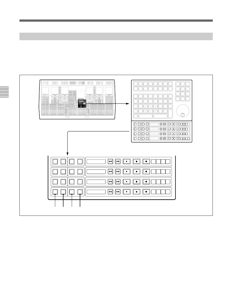
STEM monitor switch mapping
The fire-up default sets switch rows on the Control Keyboard to control
stems as:
• Remotes Row 1 - Stem A
• Remotes Row 2 - Stem B
• Remotes Row 3 - Stem C
• Remotes Row 4 - Stem D
Mapping is fully flexible via GUI and can include Stems E-H. The GUI
set-up operation is described in the following section.
Once stems have been set up, the tape sends and returns for each stem can
be switched in tandem. The switching is operable in several ways, using
the SENDS and RETS buttons by the machine remotes or using external
switches linked to GPI (General Purpose Interface) connections. Switches
may be operated locally.
4-13-4 Stem Monitor Switching