Yaskawa MotionSuite Series Machine Controller Software Manual User Manual
Page 240
MotionSuite™ Series Machine Controller Software Manual
Chapter 7: System Data Definition
7-67
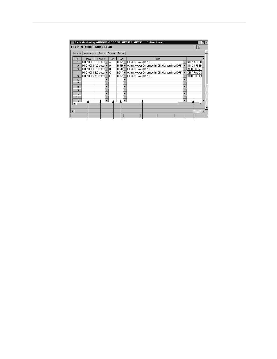
Input the configuration data. The number of fault points of the Failures data that can
be defined differs according to the type of PLC.
1. Relay
Input the relay number (bit register number). The types of registers that can be
input are S, I, O, and M.
2. Contact
Select A Contact when a fault detected with the Fault relay input into the Relay
box is in the ON state, and B Contact when a fault is detected with the Fault relay
input into the Relay box is in the OFF state.
3. Rank
Input a single character for the fault rank. As the rank is a comment, it has no
effect on Relay processing. The rank can be freely determined by the user.
4. Scan
Select the type of Relay scan.
HIGH:
High-speed processing scan
LOW:
Low-speed processing scan
5. Timing
Select the fault trace timing.
F:
Switches the fault relay ON/OFF
This designates a normal fault trace. Fault occurrence/Recovery
processing is executed at the point in time when the Fault relay
goes ON/OFF.
A:
Annunciator Unconfirmed Output ON/Confirmed Output OFF
This designates a fault in which the annunciator was used. Fault
occurrence/Recovery processing is executed when the unconfirmed
output goes ON/OFF.
1
2
3
4
5
6