2 types of definition screens, 3 definition screen call-out, Starting from the file manager – Yaskawa MotionSuite Series Machine Controller Software Manual User Manual
Page 177
MotionSuite™ Series Machine Controller Software Manual
Chapter 7: System Data Definition
7-4
7.1.2
Types of Definition Screens
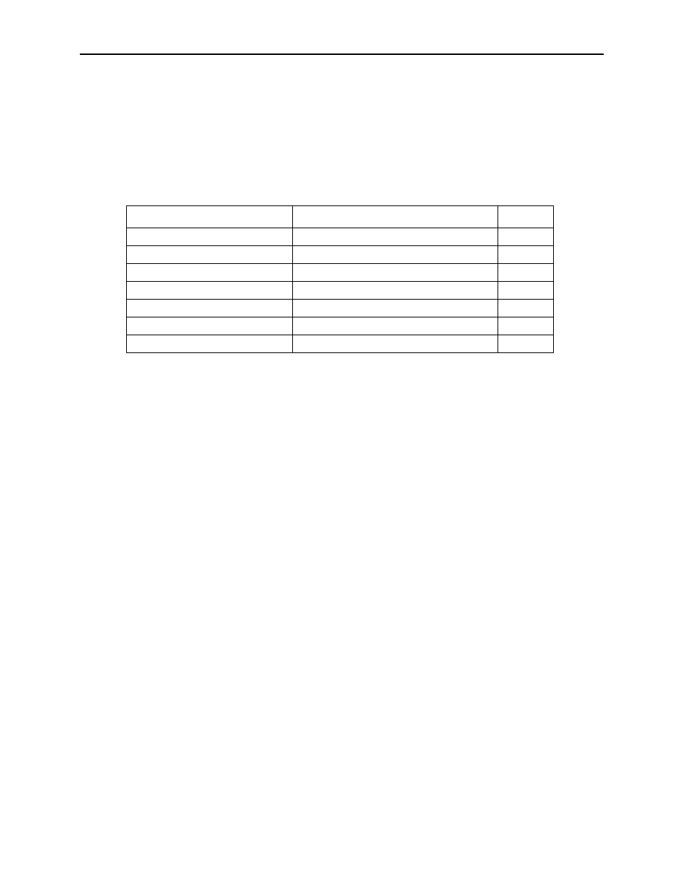
The following table lists the system data definition screens provided in the Motion-
Suite™ series machine controllers, and describes them. A in the Need box means
that this definition data must be set. Others are defined according to the system con-
figuration.
7.1.3
Definition Screen Call-out
There are two ways of starting: from the File Manager, and from the Engineering
Manager.
Starting from the File Manager
Open the desired PLC file as shown below in the tree diagram displayed in the left
window of the File Manager. The definitions file is opened upon opening a motion
folder and a definitions folder. Place the cursor on the definitions file to be operated
and double-click; the files existing in the folder are displayed in the right window of
the File Manager. Double-clicking here opens the file.
Table 1: Definition Screen Types
Definition
Description
Need
Scan Time Setting
High Speed/Low Speed scan time setting
Group Definition
Sets groups of axes for linked control
Motion Parameter Setting
Adjusts servo parameters
System Configuration
Verifies/Changes PLC set-up
Application Information
System data history
Data Trace
Defines data to be traced (oscilloscope)
Fault Monitor
Defines data for fault monitoring