Yaskawa MotionSuite Series Machine Controller Software Manual User Manual
Page 195
MotionSuite™ Series Machine Controller Software Manual
Chapter 7: System Data Definition
7-22
6. Unit
This displays the parameter units.
7. Current Value
This displays the current value of a parameter in the on-line mode. Nothing is
displayed in the off-line mode.
8. Minimum / Maximum Values
This displays the minimum/maximum values allowed for the parameters.
Note:
An input setting is immediately stored in the PLC register when the Enter key is pressed
in the on-line mode. The current value is then displayed accordingly.
Table 8: Servo Interface Command Types
Command Types
Positioning
External Positioning
Zero-point Return
Interpolation
Final Interpolation Segment
Interpolation with Position Detection Function
Set Speed Feed
Set Inch Feed
Zero-Point Setting
Acceleration Time Change
Deceleration Time Change
Filter Parameter Change
Filter Type Change
Speed Loop Gain Change
Position Loop Gain Change
Feed Forward Change
User Parameter Read
User Parameter Write
Current Generated Alarm Monitor
Alarm History Monitor
Clear Alarm History
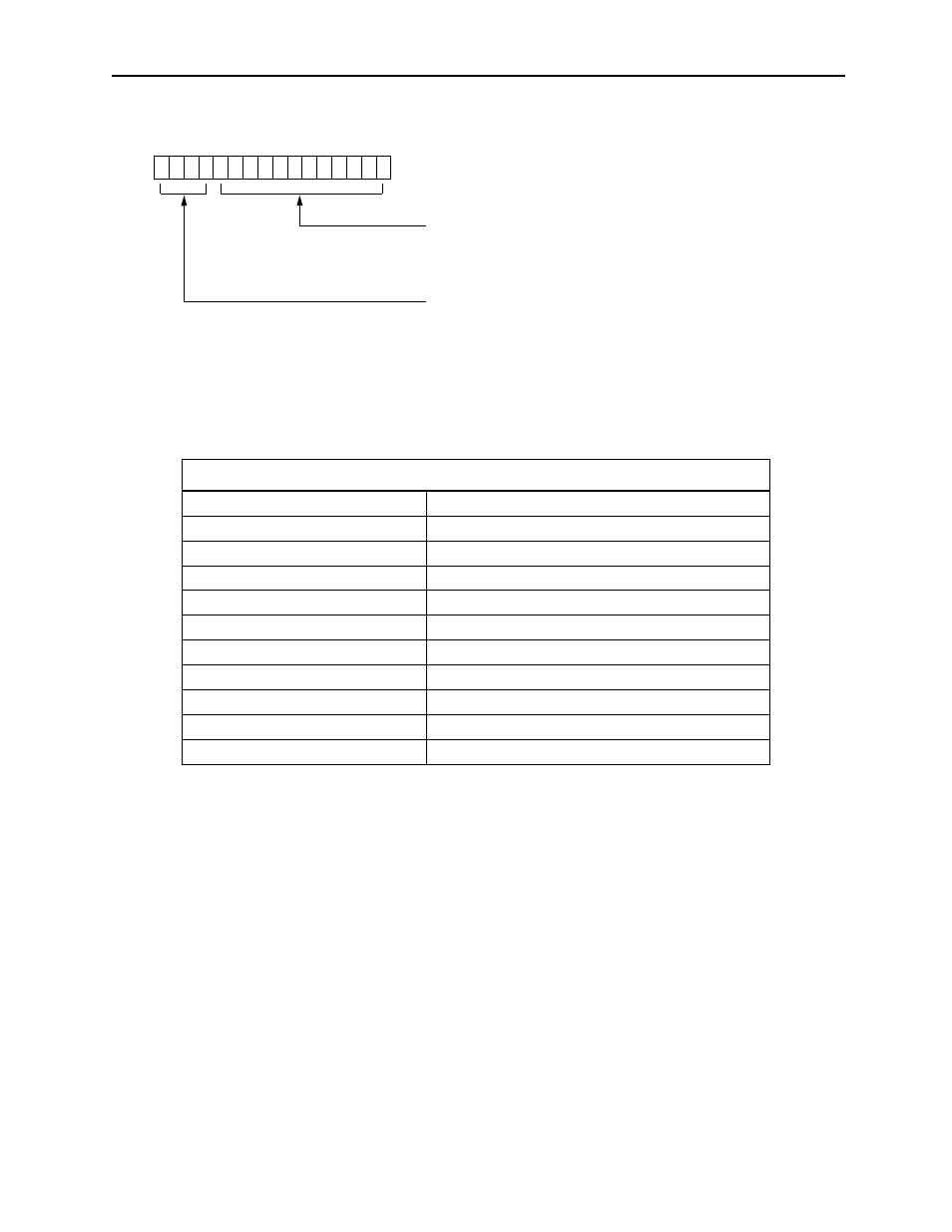
F E D C B A 9 8 7 6 5 4 3 2 1 0
Figure 6: Bit Structure of Parameter No. 42, Network Servo User Parameter Number
User Parameters (0~4095)
Number of Words (1~2)