4 system configuration, 1 structure of the system configuration window, Menu structure of the system configuration window – Yaskawa MotionSuite Series Machine Controller Software Manual User Manual
Page 203
MotionSuite™ Series Machine Controller Software Manual
Chapter 7: System Data Definition
7-30
7.4 System Configuration
The current status of the PLC can be displayed and modified in the System Configuration
window. This section describes the operation of the System Configuration window.
7.4.1
Structure of the System Configuration Window
This item deals with the menus and tabs of the System Configuration window.
Menu Structure of the System Configuration Window
See Item 7.1.3, “Definition Screen Call-out” before opening the System Configuration
window. The menus displayed in the System Configuration window are shown in
Table 11. See the item numbers shown in Table 11 when referring to the various func-
tions from the menu.
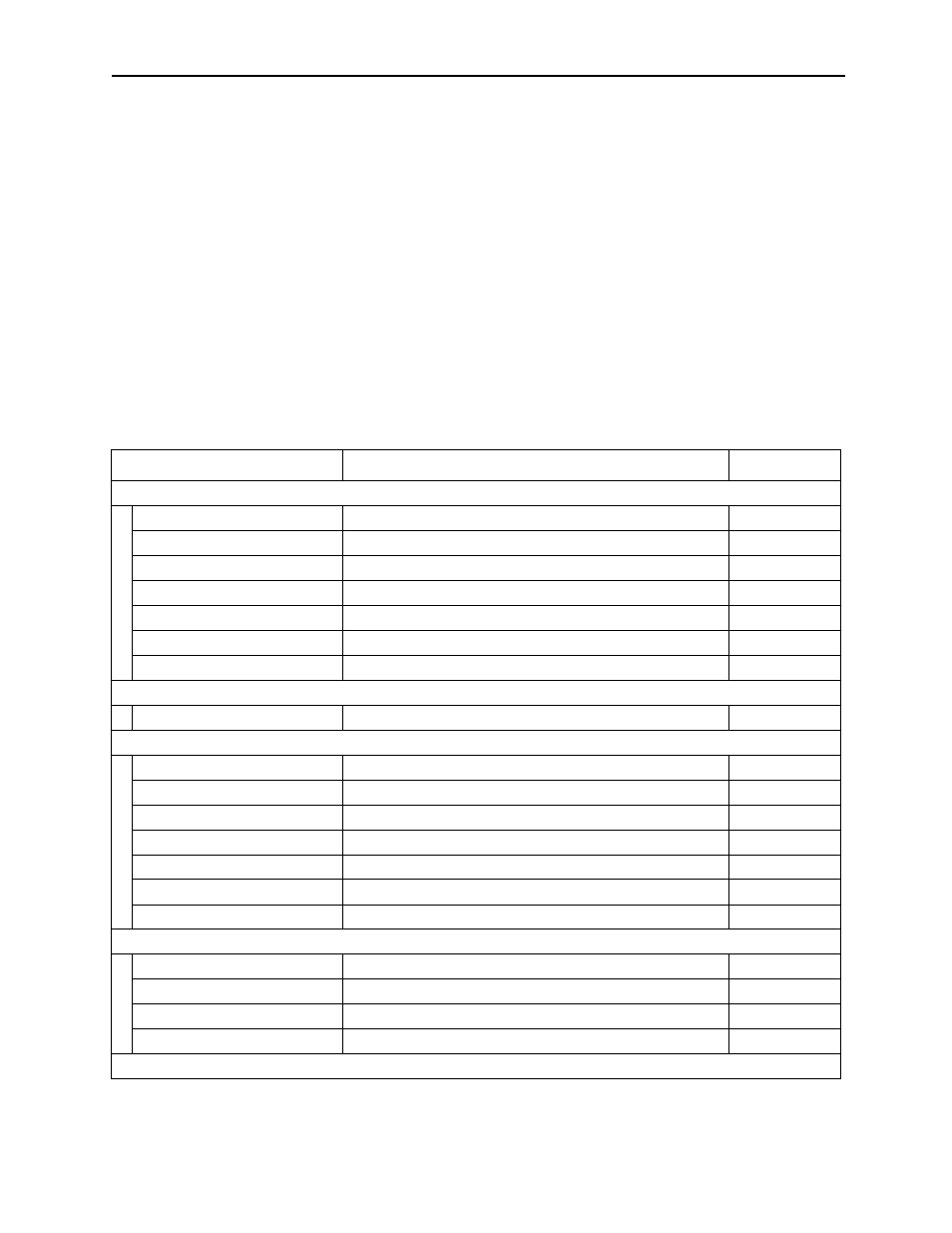
Table 11: System Configuration Window Menu
Menu
Function
Item No.
File (F)
File Manager (F)
Opens File Manager
3.4.2
Open (O)
Opens various function windows
5.1
Close (C)
Closes the System Configuration window
7.4.6
Regist User Menu (U)
Registers user menu
—
Save (S)
Saves System Configuration data
7.4.5
Print (P)
Prints document
Ch. 12
Exit (X)
Exits Engineering Manager
3.4.2
Edit (E)
Delete Assign (D)
Deletes data allocated to the global memory
7.4.3
Control (C)
Calendar (C)
Modifies calendar values
7.4.4
CPU Run (R)
Sets PLC to on-line running mode
7.4.4
CPU Stop (S)
Sets PLC to on-line stopping mode
7.4.4
Err Reset (E)
Resets detected error display
7.4.4
Mem Clear (M)
PLC memory clear
7.4.4
Mem Compact (L)
Compacts the user program for the PLC memory
7.4.4
CPU Reset (T)
Resets CPU
7.4.4
View (F)
Tool Bar (T)
Displays tool bar
3.4.3
Status Bar (B)
Displays status bar
3.4.3
Next Page (N)
Displays next tab page
7.4.1
Back Page (N)
Displays previous tab page
7.4.1
Window (W)