K2 summit/solo system connector pinouts, Aes audio – Grass Valley K2 AppCenter v.9.0 User Manual
Page 270

K2 Summit/Solo system connector pinouts
The following sections describe K2 Summit/Solo system rear panel connector pinouts.
AES Audio
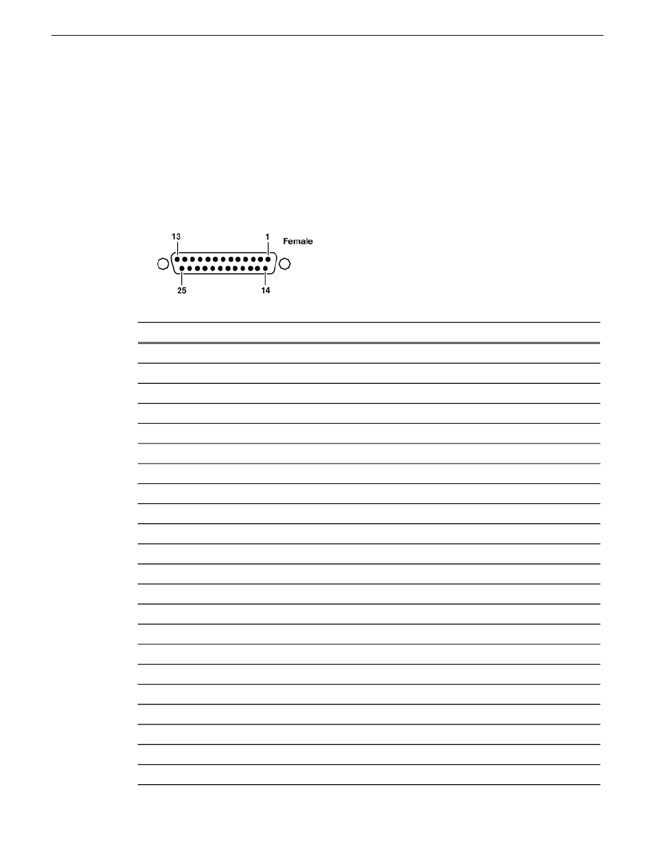
Pinouts for each channel’s AES Audio DB25 connector are as follows:
Description
Signal
Pin #
Channel Input 1&2 positive
IN_P<0>
1
Channel Input 3&4 positive
IN_P<1>
2
Channel Input 5&6 positive
IN_P<2>
3
Channel Input 7&8 positive
IN_P<3>
4
Channel Output 1&2 positive
OUT_P<0>
5
Channel Output 3&4 positive
OUT_P<1>
6
Channel Output 5&6 positive
OUT_P<2>
7
Channel Output 7&8 positive
OUT_P<3>
8
NO_C
NO_C
9
GND
GND
10
NO_C
NO_C
11
GND
GND
12
GND
GND
13
Channel Input 1&2 negative
IN_N<0>
14
Channel Input 3&4 negative
IN_N<1>
15
Channel Input 5&6 negative
IN_N<2>
16
Channel Input 7&8 negative
IN_N<3>
17
Channel Output 1&2 negative
OUT_N<0>
18
Channel Output 3&4 negative
OUT_N<1>
19
Channel Output 5&6 negative
OUT_N<2>
20
Channel Output 7&8 negative
OUT_N<3>
21
GND
GND
22-25
270
K2 AppCenter User Manual
29 October 2012
Connector pinouts
