Da-98hr, Digital input, Input patch – Teac DM-24 User Manual
Page 89: Output patch, Input monitor, Track delay, Time mode, Tc rec, Tc generator, Machine offset
11 – Machine Control/Location—DTRS devices
TASCAM DM-24 Reference Manual
89
be carried out easily from the DM-24. Consult the
documentation of your DTRS unit for full details of
how these operations affect the unit.
It is essential the unit connected directly using the
DTRS REMOTE CONTROL
connection from the
DM-24 has an ID of 1 (0 in the case of DA-88s). It is
suggested that the other units in the chain are num-
bered in order following this (but this is not essen-
tial). Remember that all chains of DTRS units should
be terminated.
If the DTRS units are to be word clock slaves of the
DM-24, the dedicated word clock input of the DTRS
unit connected directly to the DM-24 should be con-
nected to the word clock sync output of the DM-24,
and the clock source set to WORD. Subsequent units
in the chain will receive their word clock information
directly through the REMOTE connections, and do
not require dedicated word clock connections.
Some specific information concerning the individual
models in the range is provided here.
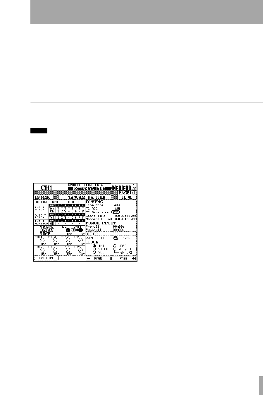
DA-98HR
This screen (accessed using soft keys 3 and 4) allows
the remote control of the following parameters.
NOTE
When the DA-98HR is set to any sampling frequency
other than the eight base-frequency track setting
(including dual-frequency or quad-frequency recording
modes), the number of tracks shown on screen whose
parameters are shown will differ from those shown
here. In addition, some features are only available in
the eight track mode. Consult your DA-98HR documen-
tation for full details of some of these features.
DIGITAL INPUT
Use this to change between the
TDIF and AES/EBU inputs.
INPUT PATCH
The input patchbay can be viewed
and set using this screen. Navigate around the matrix
using the cursor keys.
OUTPUT PATCH
View and set the output patch-
bay using this part of the screen.
INPUT MONITOR
The individual track monitor-
ing can be set and viewed with this part of the screen.
TRACK DELAY
Can be set individually, or
together. Move the cursor to the appropriate row and
use the appropriate PODs to set the individual track
or POD 3 to set all values together, and confirm with
the on-screen
SET
button.
Change between samples and milliseconds as the
unit of measurement, using POD 4.
TIME MODE
Select between ABS and TC timing
reference.
TC REC
Arm and unarm the timecode track using
this on-screen button.
TC Generator
Start and stop the DA-98HR gener-
ator, as well as setting the start time. Individual
hours, minutes, seconds and frames are set by navi-
gating to the appropriate field.
Machine Offset
Set this value here. Individual
hours, minutes, seconds and frames are set by navi-
gating to the appropriate field.
PUNCH IN/OUT
Set the preroll and postroll val-
ues.
DITHER
Set the dither type to off, rectangular or
triangular.
VARI SPEED
Can be set on or off, and the value
changed to ±6.0% relative to the nominal pitch.
CLOCK
Choose between the different available
clock sources for the DA-98HR:
INT
(internal),
VIDEO
,
SLOT
,
WORD
and the AES/EBU inputs. If the
AES/EBU inputs are selected, the pair to be used as
the clock source can then be chosen.