10 – monitoring, Control room monitoring, Control room outputs – Teac DM-24 User Manual
Page 73: Control room signal selection, Control room outputs control room signal selection
TASCAM DM-24 Reference Manual
73
10 – Monitoring
The DM-24 contains a sophisticated monitoring sys-
tem which allows different mixes to be set up in the
control room and the studio, as well as an integral
talkback microphone, lineup oscillator, etc.
Control room monitoring
The control room (CR) monitoring section, which
also includes two stereo headphone jacks, is located
to the right of the stereo meters.
Control room outputs
As might be expected, the control-room output sig-
nals are always output from the balanced 1/4” analog
CR (BAL)
connectors (+4 dBu)
.
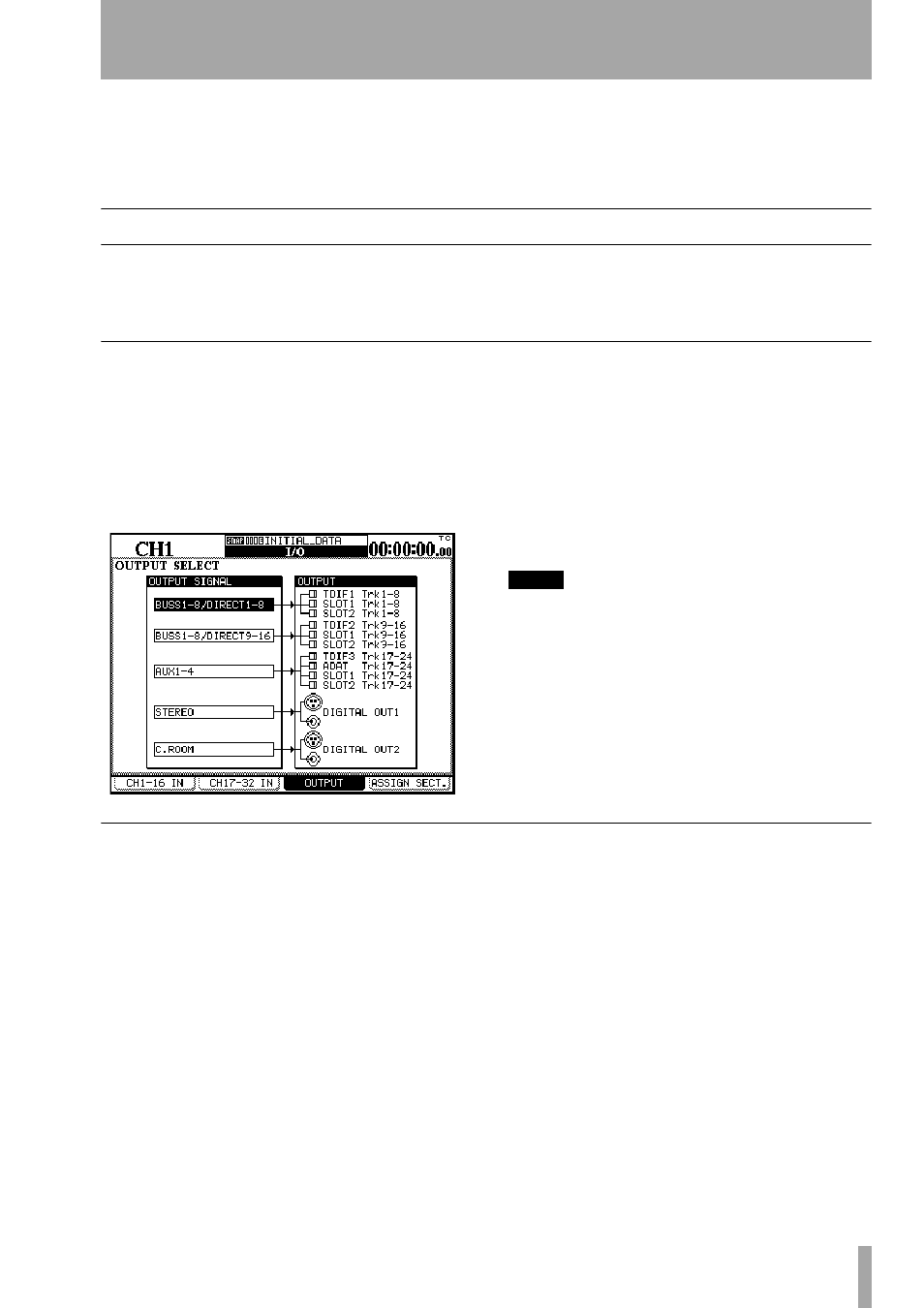
However, if the digital outputs are not being used for
any other purpose, the
I/O OUTPUT
screen may be
used to assign the control room outputs to either the
DIGITAL 1
or
DIGITAL 2
sets of outputs.
From the I/O screen, use the third soft key to bring up
the output selection screen.
Move the cursor to either of the selection boxes
opposite the
DIGITAL OUT1
or
DIGITAL OUT2
selector.
Turn the dial until
C.ROOM
is shown, and press
ENTER
.
The control room signal will now be output from the
selected digital outputs.
NOTE
The signal is sent from both the XLR-type jack and the
RCA jack simultaneously. The output format (AES/EBU
or SPDIF) is set using the DIGITAL display FORMAT sub-
screen.
The level of the signal sent from the analog outputs is
adjusted by the
CR
control.
The level of the signal sent from the headphone jacks
(both headphone jacks together) is adjusted using the
PHONES
control.
Control room signal selection
There are four signal selection keys for the control
room signal.
These are:
STEREO
,
SEL 1 (AUX 1-2)
,
SEL 2 (D IN
1)
,
SEL 3 (2 TR IN)
.
The first of these,
STEREO
, is hard-wired. That is,
when this option is selected, the control room outputs
as selected above will always output the stereo buss
signal.
The other three keys are “soft”, and may be patched
internally to output signals other than those given as
the defaults (in parentheses on the panel).
The default settings may be useful when used in the
following way, however:
When recording, aux sends 1 and 2 may be used as
the studio cue mix, leaving aux sends 3 through 6 for
effect use, etc. By using the
SEL 1
key set to the
default
AUX 1-2
setting, it is therefore possible for
the control room monitor to echo the signal sent to
the studio.
When mixing, the mastering devices (connected to
the stereo buss) may be digital or analog. The
SEL 2
key is by default set to the first digital input (whether
this is the XLR-type connector or the RCA jack is
determined in the channel
IN
screens of the
I/O
setup)
and can therefore be used for monitoring the replay
from the digital 2-track mastering device.
The
SEL 3
key is by default assigned to the analog 2-
track inputs
. These are typically used to monitor