Dynamics diagram, Gates/expanders, Gate – Teac DM-24 User Manual
Page 66: Threshold, Range, Hysteresis, Gate attack time, Gate hold time, Gate decay time, Expander
8 – Dynamics processors—Dynamics diagram
66
TASCAM DM-24 Reference Manual
Dynamics diagram
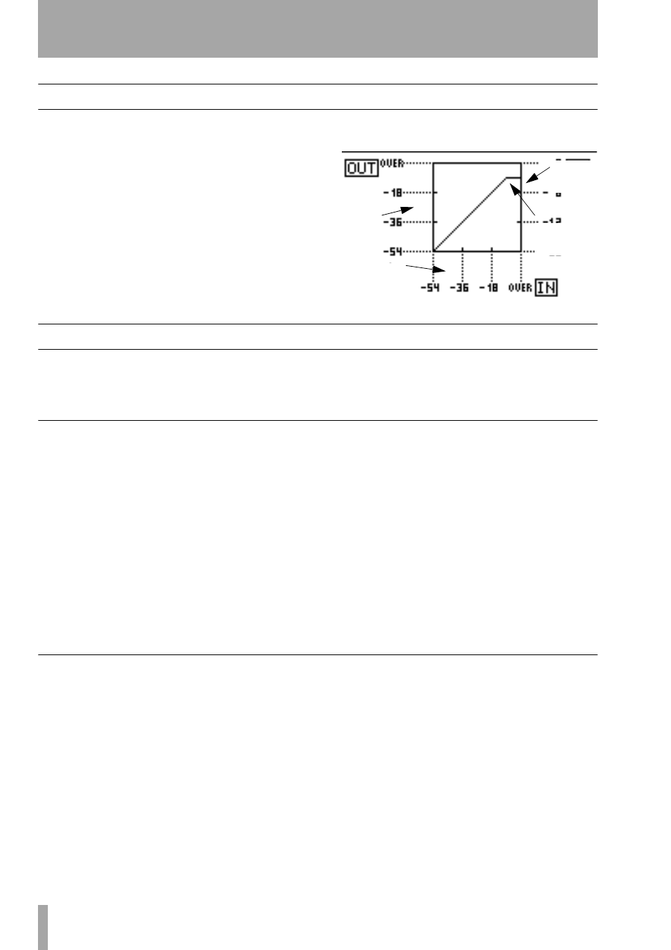
The following display provides a graphical represen-
tation of the compressor settings, as shown below. As
the signal is fed through the compressor, bargraph
meters are shown on the appropriate scale:
Gates/expanders
The following parameters affect the gate and
expander, if these have been assigned to the selected
channel.
Gate
Threshold
(
THRESH
), controlled by the POD 1
knob, allows the setting of the threshold at which the
gate will open. Variable from
-80dB
to
0dB
in 1dB
steps.
Range
(
RANGE
), controlled by the POD 2 knob, sets
the gate range, from
60dB
to
0dB
in 1dB steps.
Hysteresis
(
HYST
), controlled by the POD 3 knob,
from
0dB
to
24dB
in 1dB steps.
Gate attack time
(
ATTACK
), controlled by the
POD 1 knob on the last row. Variable from
0ms
to
125ms
in 1ms steps.
Gate hold time
(
HOLD
), controlled by the POD 2
knob on the last row. Variable from
0ms
to
990ms
in
100 steps.
Gate decay time
(
DECAY
), controlled by the POD
3 knob on the last row. Variable from
50ms
to
5.0s
.
From 5ms to 200 ms, the steps are 5ms apart; from
200ms to 300ms, the steps are 10ms apart; from
300ms to 500ms, the steps are 20ms apart; from
500ms to 1.00 s, the steps are 50 ms apart; from 1.00s
to 3.00s, the steps are 0.1s apart; and from 3.00 s to
5.00s the steps are 0.2s apart.
Expander
Threshold
The threshold of the expander function,
from
–48dB
to
0dB
, in 1dB steps.
Ratio
The ratio of the original signal relative to the
expanded signal. Values are 1:1, 1:2, 1:4, 1:8, 1:16,
1:32, 1:64.
Attack
The attack time of the expansion effect.
From
0ms
to
125ms
in 1ms steps.
Release
The release time of the expansion effect.
From 5ms to 5.00 seconds.
From 5ms to 200 ms, the steps are 5ms apart; from
200ms to 300ms, the steps are 10ms apart; from
300ms to 500ms, the steps are 20ms apart; from
500ms to 1.00 s, the steps are 50 ms apart; from 1.00s
to 3.00s, the steps are 0.1s apart; and from 3.00 s to
5.00s the steps are 0.2s apart.
Output
levels
Gain
reduction
Compressor
“knee”
Input levels