Module faders and selection, etc, Transport and automation control, 4 – parts of the dm-24—top surface – Teac DM-24 User Manual
Page 33
4 – Parts of the DM-24—Top surface
TASCAM DM-24 Reference Manual
33
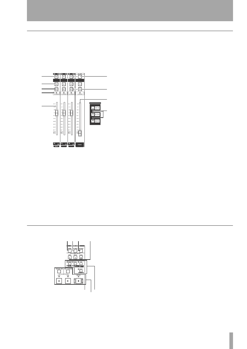
Module faders and selection, etc.
The module faders are arranged in layers (see “Fader
layers” on page 18). Accordingly, the 16 module fad-
ers are used to control all 32 inputs, the six aux sends
and the output buss sends as shown on the pre-
printed labels above and below each channel strip.
Note that a wipe-off surface is provided (below the
REC
keys) for you to write in soft pencil the func-
tions of the channels (equipment connected to the
DM-24, etc.).
m REC key
These keys, with integral indicator,
are used to set and show the recording status of tracks
of devices controlled by the DM-24.
n SEL keys
These keys, with integral indica-
tors, are used to select the modules for editing opera-
tions, as well as for stereo linking and other editing
functions. The indicators light to show which module
has been selected.
o MUTE keys
These keys, with integral indica-
tors, show the muting status of the modules. When
used with the solo modes, they give instant indication
of what module(s) are selected for soloing.
p OL/STATUS indicators
These indicators
may be selected using software to show either over-
load to the input channels or the current status of the
channel when automation operations are being car-
ried out. See “OL/STATUS LED TYPE” on page 20
for details of these settings.
q Module faders
These 100mm motorized
faders are labeled from
∞ (full cut) to
+10
(dB). The
0
position may be set to be equivalent to the appro-
priate full-scale value using software.
r ALL SAFE key
This key, with integral indi-
cator, is used to “safe” any tracks of recording
devices controlled by the DM-24.
s SOLO key
This key, with integral indicator,
is used to enable the soloing function as selected in
“SOLO” on page 22.
t STEREO fader
This fader does not change
function as the layers are changed, but controls the
level of the stereo outputs.
It is labeled from
∞ (full cut) to
0
(full scale).
u LAYER STATUS keys
These keys (with
integral indicators), as explained in “Fader layers” on
page 18, change the function of the modules to pro-
vide access to the different fader layers.
Transport and automation control
This controls in this section provide remote control
facilities for recording devices, etc. attached to the
DM-24.
v REPEAT key
This key, with integral indica-
tor, is used to control repeat playback.
w ALL INPUT key
Provides input monitoring
for all tracks on the selected unit(s).
x AUTO MON key
Provides automated
switching between input and off-tape monitoring.
y AUTO PUNCH IN/OUT keys
Typically
used with the DTRS family of recorders.
z Transport keys and indicators
The
exact function of these keys (
REW
,
F FWD
,
STOP
,
PLAY
and
RECORD
) and indicators depends on the
device currently selected for external control.
*
(
)
Q
W
E
T
R
Y
U I O
P
A
S