Output signals, Eight output busses, Six aux busses – Teac DM-24 User Manual
Page 37: Stereo master outputs, Direct outputs, Physical outputs, Tdif-1 connectors, Adat out connector, Slot cards, Assignable sends
5 – Setting up the I/O—Output signals
TASCAM DM-24 Reference Manual
37
Output signals
The following are the signals output from the DM-24
(excluding the monitoring signals):
Eight output busses
These busses are typically
routed to the built-in multi-track outputs (TDIF and
ADAT) or to the optional slot cards.
Six aux busses
These six aux busses may be
routed to the assignable sends, as well as to the inter-
nal effect units.
Stereo master outputs
These stereo outputs
are typically used as the sum of the mixed output
busses (except in surround mode).
Direct outputs
The signals from the channels can
be output directly, not passing through busses, etc. to
the connectors (TDIF, ADAT, slot) below.
Physical outputs
This excludes the monitoring outputs (control room,
studio, etc.).
TDIF-1 connectors
These connectors are used as
outputs as well as inputs, carrying eight channels
each in normal-frequency mode. In dual-frequency
mode situation this is different.
ADAT OUT connector
This lightpipe connector
can be used as outputs from busses or as direct out-
put. It carries eight channels in normal-frequency
mode.
Slot cards
These may act as outputs, depending on
the cards installed.
Assignable sends
These sends may be used as
either analog insert sends or as aux sends.
Digital outputs (x 2)
Can be assigned to output
the stereo buss, adjacent pairs of busses, adjacent
pairs aux busses or the control room source.
STEREO OUTPUTS (L, R)
Used as the analog
outputs for the stereo master buss.
Patching between input and return
The DM-24 allows you to switch between the
assigned inputs and returns for channels 1 through 24
without having to connect or disconnect cables. The
sources for channels 25 through 32 are not selectable
in this way.
These switches are accessed from the I/O screens.
1
With the
SHIFT
indicator lit, press the
I/O
key.
2
Press either the first or second soft key to
bring up the channel assignment screens.
The on-screen channels have two columns, the
sources, and the destinations, with a “patch cable”
connecting them.
The source column has two alternative sources for
each channel: the input (top) and the return (bottom)
sources.
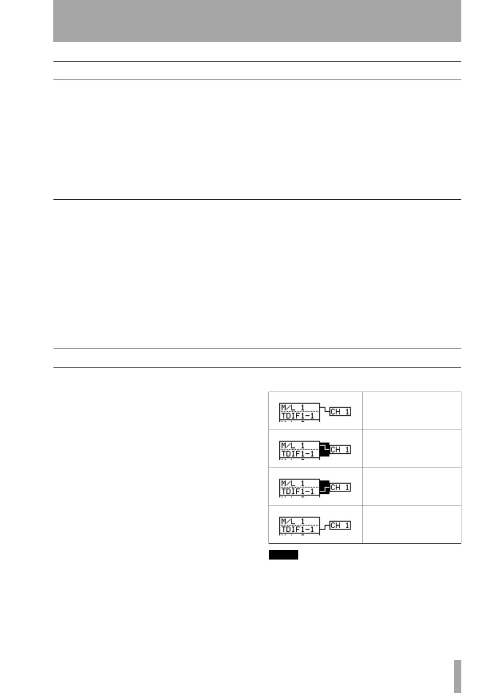
Move the cursor to the “patch cable” and turn the
dial.
3
Press
ENTER
to confirm the change.
NOTE
This switching can also be done in the fourth MODULE
screen (“Channel source (CH SOURCE)” on page 58).
Mic/line input 1 is routed to
input channel 1
The cursor is moved to high-
light the “patch cable”
The dial has been turned to
“repatch” TDIF1 channel 1 to
channel 1
The
ENTER key has been
pressed to confirm the re-
patching process.