High sampling frequency, Fs status, D-in manual setup – Teac DM-24 User Manual
Page 25: Word sync in, Tdif interfaces, Adat, Aes3, Cascade master, Word phase, Checking the clock sources
3 – System-wide options—DIGITAL screens
TASCAM DM-24 Reference Manual
25
A popup appears with an unlocked indication and an
error message. If this happens, correct the clock
source, and press the
ENTER
key to dismiss the
popup.
When a clock source is selected, the clock indicators
to the left of the console change to show the current
clock frequency and the
EXT CLOCK
indicator lights
if an external clock has been selected as the clock
source.
High sampling frequency
To select high sam-
pling frequency mode, select
Hi-Sampling
, and press
ENTER
.
When the DM-24 changes to high sampling fre-
quency, a popup message is shown on screen, telling
you to turn off the DM-24 and turn it on again, to
enter high sampling frequency mode.
NOTE
Remember to turn down the monitor value, etc. to
avoid “thumps” which may damage equipment when
turning the DM-24 on and off.
The clock source screen changes in the case of high
sampling frequency being selected.
NOTE
Many other display screens will change if high sampling
frequency is selected. These differences are described in
a separate chapter (“High sampling frequency” on
page 112).
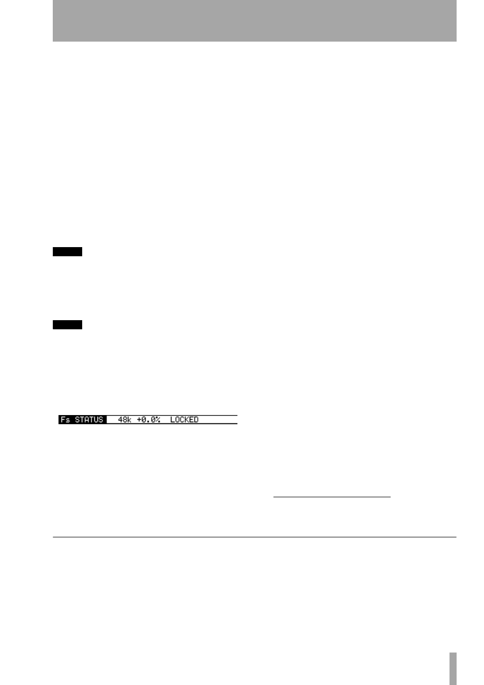
Fs Status
This shows the current sampling fre-
quency status (base frequency, deviation from the
nominal value, and the locked/unlocked status).
Select the appropriate clock source. In the case of the
internal clocks, the frequency may be chosen as
either 44.1kHz or 48kHz. In most other cases, the
frequency is pre-determined.
There are one or two other points to be borne in mind
when making these settings.
D-IN MANUAL SETUP
A manual selection may
be made in the case of one of the digital inputs (
D-IN
)
being selected as a clock source with sampling fre-
quency conversion. Select the appropriate destination
frequency here.
Whether the RCA or XLR connector is used as the
clock source is selected in the
I/O
screens (“Digital
inputs” on page 39), not here.
WORD SYNC IN
Since the frequency information
of any signal received at the
WORD SYNC IN
con-
nector is not used by the DM-24, if this source is to
be selected as the word sync source for the DM-24,
the sampling frequency must be explicitly selected.
TDIF interfaces
In the case of the TDIF-1 inter-
faces card), the device attached to the card source is
shown as either a
DA-88
(DA-88 DTRS recorder) or
OTHER
(another type of recorder connected through
the TDIF-1 interface). If the indicator shows DA88,
then I/O data is truncated to 16 bits, otherwise I/O is
carried out at 24 bits.
ADAT
In the case of an ADAT “lightpipe” interface
card, the
INT
setting, allowing the ADAT to act as the
clock master, is always selected.
AES3
In the case of an AES/EBU interface card,
there are four different sources (the four AES/EBU
inputs
1
) which may be selected as the word clock
source for the DM-24.
CASCADE MASTER
If the DM-24 has been set
up as a cascade slave (using the
DIGITAL SLOT
screen), then this cascade master option is automati-
cally selected, and this setting cannot be changed (the
master is free, of course, to accept its clock from any-
where).
Word phase
The phase of the word sync signal
can be inverted independently for input and output
relative to normal. Use the phase correction facilities
to match word clocks from different equipment.
Checking the clock sources
To give details of all possible sources, move the cur-
sor to the on-screen
CHECK
button, and press
ENTER
.
A popup message appears. Use the
ENTER
key to
continue with the check (cancel using any of the cur-
sor keys).
The DM-24 mutes, and a panel appears with details
of all possible clock sources. Press
ENTER
once
again to dismiss this panel.
1. This changes to two inputs when high fre-
quency sampling is selected.