Other ways of changing values, Using the faders to change values, 2 – user interface—scope of controls – Teac DM-24 User Manual
Page 14
2 – User interface—Scope of controls
14
TASCAM DM-24 Reference Manual
Other ways of changing values
The
JOG/DATA
dial can also be used to change
parameter values.
1
Use the cursor keys to move the cursor
(sometimes shown by a blinking thick box
surrounding the parameter to be changed,
and sometimes by a
ƒ
symbol beside the
parameter to be changed.
2
When the parameter to be changed is high-
lighted as described above, use the entry dial
to set the value (it starts to flash), and the
ENTER
key to confirm the value set with the
dial.
Alternatively, if the parameter is an on-off
switching button or a checkbox (a number of
checkboxes can be checked individually),
press the
ENTER
key when the cursor is next
to the button or checkbox.
If the parameter is a “radio button” (one of a
number of alternative options), simply high-
light another radio button in the same group,
and press the
ENTER
key to change the state
of the buttons in the group.
NOTE
In some screens, (for example the module screens), the
active area is marked by a flashing box. The dial is then
used for navigation, rather than for setting values.
There are other screens, where the dial is chiefly, but
not exclusively, used for navigation (e.g. the OPTION
SETUP screen (“SETUP” on page 20). If the dial is used
for numerical data entry in such cases, it is necessary to
press ENTER (the value flashes) before starting to edit
the value with the dial, and ENTER once again after
editing to confirm the value.
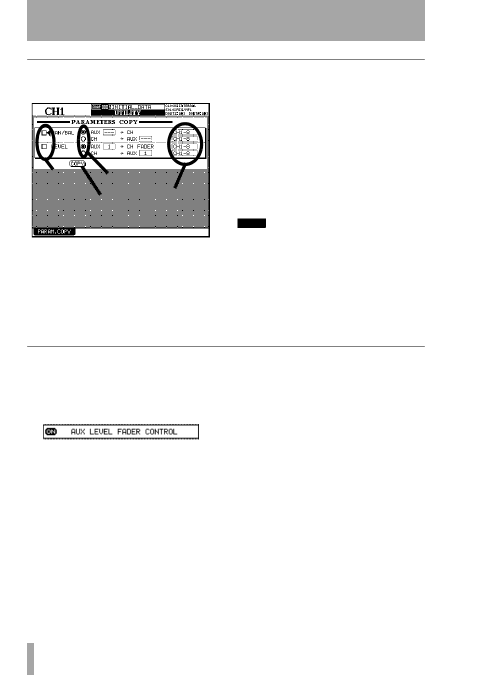
Using the faders to change values
In the global screens, there is often a special on-
screen button, allowing the setting of the values in
the screen directly using the faders.
To enable this feature, turn the on-screen
FADER
CONTROL
button to
ON
.
The name of this button is prefixed by the title of the
screen (here it is an
AUX LEVEL
screen which is being
edited).
When the button is turned on:
• The faders move to reflect the values set for the
current parameter
• The fader layer key starts to flash (if it is a channel
module layer and not the master layer—see “Fader
layers” on page 18). This flashing key shows that
the faders are not currently acting as channel faders
and that moving the faders will change the cur-
rently selected parameter, not the module’s signal
level.
• Moving the fader of a channel changes the value of
the current parameter.
• Using the POD to change the value of a channel’s
parameter moves the corresponding fader if the
layer is active. If the layer is not active, the fader
will be moved to the new position when the layer is
made active.
The status of the fader control setting is memorized
between screens (and even when the DM-24 is turned
off and on again). It is therefore possible for the fad-
ers to move when the screen is changed.
The layer continues flashing as long as the faders are
not controlling the channel levels.
Parameter values
Checkboxes
Radio buttons
On/off button
edited without the
ENTER key.