Encoders used as eq gain controls, Encoders used as eq frequency controls, Encoders used as q controls – Teac DM-24 User Manual
Page 16: 2 – user interface—rotary encoders (ring leds)
2 – User interface—Rotary encoders (ring LEDs)
16
TASCAM DM-24 Reference Manual
• EQ gain controls, where the gain of the four EQ
bands is adjusted using these encoders. The
encoder
EQ GAIN
indicator is lit in this case.
• AUX send level controls, where either the encoder
AUX 1
through
4
indicators or the
AUX 5
and
6
indicators are lit (in the latter case, only the two
leftmost encoders have any function).
See the appropriate section on module operations
(“Module operations” on page 49) for full details of
the parameters controlled here.
NOTE
The option described in “Fine value settings using the
PODs” on page 13 also affects the operation of these
encoders when used in conjunction with the 2ND F.
key.
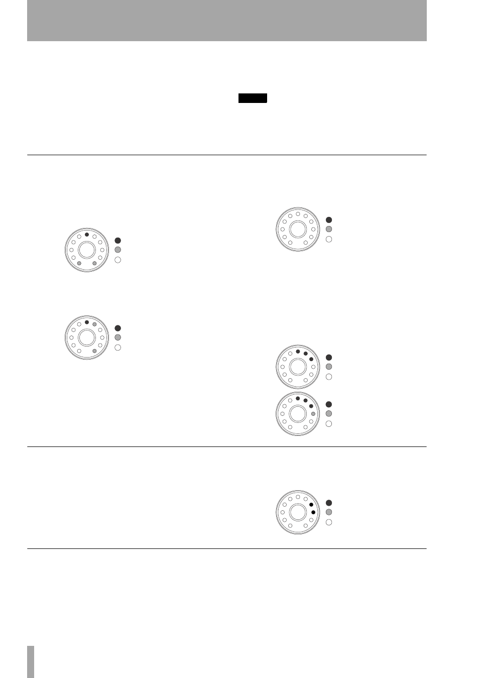
Encoders used as EQ gain controls
When the encoders are used as EQ gain controls, a
unity gain (neither cut nor boost) is represented by
the sixth (center) LED being lit, and the two LEDs at
the extreme clockwise and counterclockwise posi-
tions “half-lit” (dimmed).
When the encoder is near the center position, but not
quite there, the LED next to the center is lit, as well
as the “end” LED on the appropriate side:
If the EQ band is set as a high-pass for low-pass filter
or is used as a notch filter (depending on the band),
all LEDs around the rotary encoder are off:
When the encoder is turned either clockwise or coun-
terclockwise, to boost or cut the gain respectively, the
end LEDs go out, and the LEDs on the appropriate
side of the center light (the more the cut or boost, the
more LEDs will light). “Half steps” are shown by
dimmed LEDs at the end of the chain. The illustra-
tions below show a relatively small amount of gain
applied, and then a little more gain:
Encoders used as EQ frequency controls
When the encoders are used to set the frequency con-
trolled by an EQ band, only one or at most two LEDs
are lit at any one time.
As the knob is turned clockwise, the ring LEDs light
in turn, representing the position of the knob
“pointer”. For greater accuracy, intermediate values
are shown by two LEDs being lit simultaneously, as
in the illustration below:
Encoders used as Q controls
The Q of an EQ band refers to the width of the filter
when it is in notch or peak mode (but not in shelf or
= on
= dimmed
= off
= on
= dimmed
= off
= on
= dimmed
= off
= on
= dimmed
= off
= on
= dimmed
= off
= on
= dimmed
= off