Return modules, Digital inputs, Return modules digital inputs – Teac DM-24 User Manual
Page 39
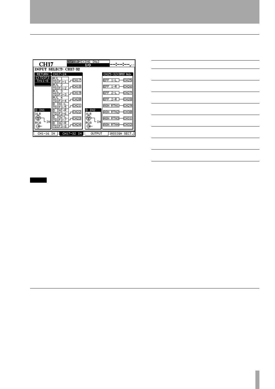
5 – Setting up the I/O—Assigning inputs to channels
TASCAM DM-24 Reference Manual
39
Return modules
Return sources are available for channels 1 through
24 (channels 25 through 32 are input only).
The return options for each group of eight channels
are selected by moving the cursor to the
RETURN
field
at the left of the list of channels, and using the dial to
select from the available options.
Press
ENTER
to confirm the setting.
NOTE
If a slot card has not been fitted, an error message
appears. Press ENTER to dismiss the message.
Each group of eight channels is assigned to use the
same return source block (though it is possible to mix
inputs and returns within the same block).
It is important to note the following:
• The returns from TDIF1-1 cannot be assigned and
used at the same time as the returns from a card fit-
ted in slot 1.
• The returns from TDIF1-2 cannot be assigned and
used at the same time as the returns from a card fit-
ted in slot 2.
• The returns from TDIF1-3 cannot be assigned and
used at the same time as the returns from the inter-
nal ADAT connector.
The first 24 channels may have the following sources
assigned to them as returns:
As can be seen, it is possible for the same return to be
assigned to more than one channel at the same time
(of course, it is not possible for one channel to accept
the signal from more than one return at the same
time).
Although the return module for each block can be
selected, the channels of the module cannot be
changed. For example, if an MTR return is assigned
to channels 1–8, track 2 of an MTR cannot be
assigned to channel 1. Track 3 can only be assigned
to TDIF channel 3 (in the TDIF1, TDIF2, TDIF3
return source blocks), or ADAT channel 3, etc.
Note, though that when slot cards are fitted, the num-
ber of the channel in the slot card may be offset by 8
or 16, so that channel 9 (or 17) of slot card 2 may be
assigned to channel 1, etc.
Digital inputs
Each digital input has two connectors; an XLR-type
connector and an RCA pin jack. One of these is
selected for input as described here.
These connectors can both be used for either AES/
EBU or SPDIF data, and the data format is automati-
cally detected by the DM-24—no settings are neces-
sary to choose the data format.
See “The FORMAT screen” on page 26 for details of
how to set the parameters for sampling frequency
conversion, etc. at these inputs.
However, although there are two physical connectors
for these inputs, the audio data for an input can only
be accepted from one of these connectors at any one
time.
Channel
Return signal
1,9,17
TDIF1-3 Trk1 / Slot1-2 Trk1 / Slot1-2 Trk9 /
Slot1-2 Trk17 / ADAT Trk1
2,10,18
TDIF1-3 Trk2 / Slot1-2 Trk2 / Slot1-2 Trk10 /
Slot1-2 Trk18 / ADAT Trk2
3,11,19
TDIF1-3 Trk3 / Slot1-2 Trk3 / Slot1-2 Trk11 /
Slot1-2 Trk19 / ADAT Trk3
4,12,20
TDIF1-3 Trk4 / Slot1-2 Trk4 / Slot1-2 Trk12 /
Slot1-2 Trk20 / ADAT Trk4
5,13,21
TDIF1-3 Trk5 / Slot1-2 Trk5 / Slot1-2 Trk13 /
Slot1-2 Trk21 / ADAT Trk5
6,14,22
TDIF1-3 Trk6 / Slot1-2 Trk6 / Slot1-2 Trk14 /
Slot1-2 Trk22 / ADAT Trk6
7,15,23
TDIF1-3 Trk7 / Slot1-2 Trk7 / Slot1-2 Trk15 /
Slot1-2 Trk23 / ADAT Trk7
8,16,24
TDIF1-3 Trk8 / Slot1-2 Trk8 / Slot1-2 Trk16 /
Slot1-2 Trk24 / ADAT Trk8