Channel source (ch source), Gate switch (gate sw), Aux 1 and 2 source (aux 1-2 source) – Teac DM-24 User Manual
Page 58: Compression insert (comp insert), Compressor switch (comp sw), Assignable insert position (assign insert), Assignable insert switch (assign ins sw), Phase switch (f), Digital delay time (delay), 7 – module operations—setup screen
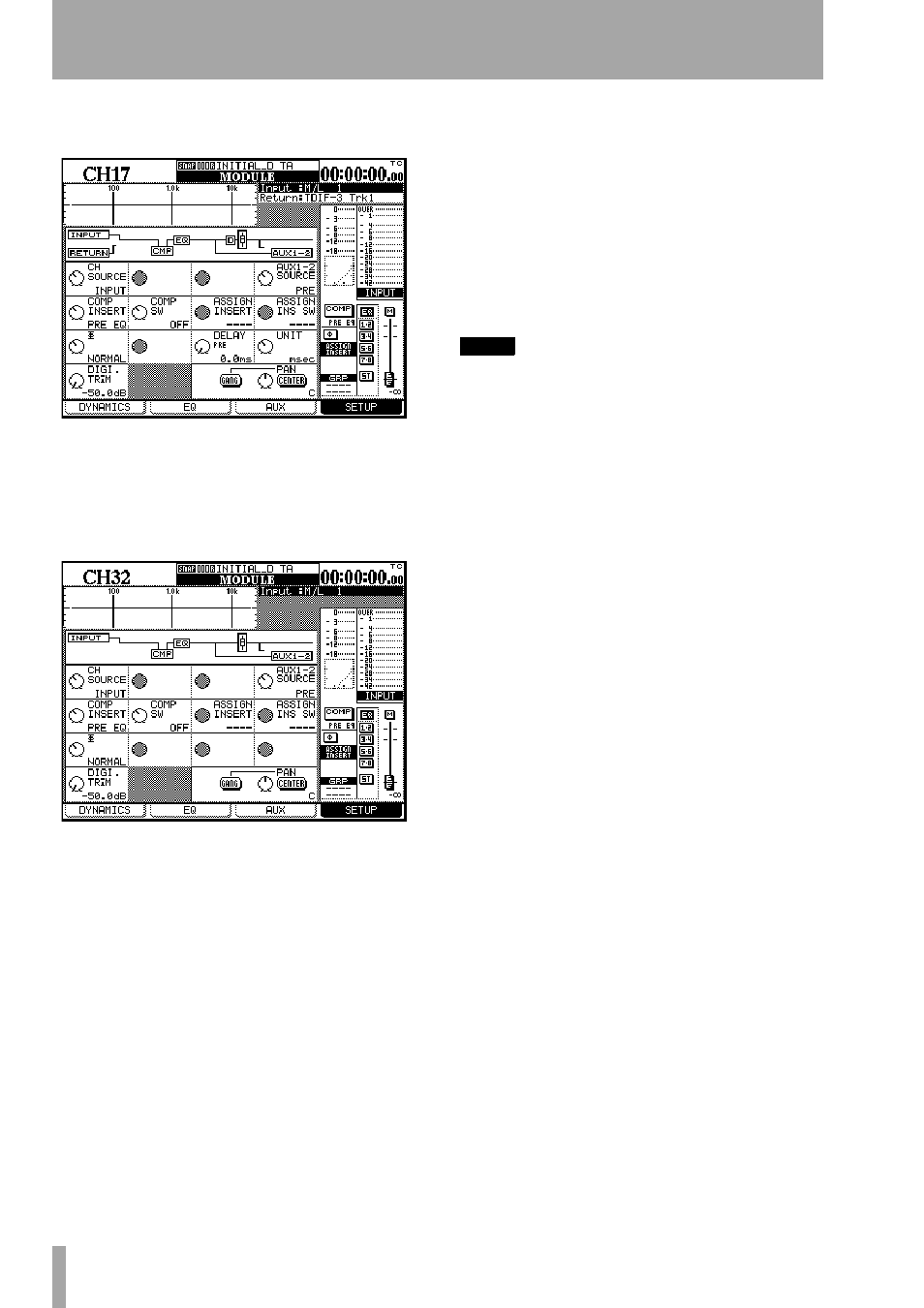
7 – Module operations—Setup screen
58
TASCAM DM-24 Reference Manual
32 have slightly different screens, reflecting the dif-
ferent configuration:
Channels 17 through 32 have no gate available.
The aux 1-2 sends are more limited in the choice of
their source points (no return available)
Channels 25 through 32 have no channel digital
delay available.
The controls available on these screens (through the
PODs or through the cursor keys and data dial) are:
Channel source (CH SOURCE)
This is a 2-way
switch. Turning POD 1 (top row) counterclockwise
selects the input (
INPUT
) source, and turning it clock-
wise selects the return (
RETURN
) source (channels 1
through 24 only). Both of the actual sources (input
and return) are defined in the I/O screen, not here.
The display at the top left of the screen is updated, as
is the block diagram.
Gate switch (GATE SW)
This (POD 2) turns the
gate (if available) on (clockwise) or off (counter-
clockwise). Channels 1 through 16 only.
Aux 1 and 2 source (AUX 1-2 SOURCE)
This (POD 4) selects the source for the Aux 1 and 2
sends to be either pre-fader (
PRE
), post-fader (
POST
)
or the return associated with the module (
RETURN
).
This selection is available in this screen because
these aux sends may be used effectively as studio
monitor sends, and flexibility is therefore a useful
feature here.
For channels 17 through 32, only the pre and post
options are available here.
NOTE
Note that even if aux sends1 and 2 are unlinked, the
settings of both are modified together using this con-
trol.
Compression insert (COMP INSERT)
This
selects the position for the compressor insert (if
assigned) to be either pre-EQ (
PRE EQ
, counterclock-
wise) or post-EQ (
POST EQ
, clockwise).
Compressor switch (COMP SW)
This switch
(POD 2) turns the compressor (if assigned) either off
(
OFF
, counterclockwise) or on (
ON
, clockwise).
Assignable insert position (ASSIGN
INSERT)
This (POD 3) allows the positioning of
the assignable insert in the module chain. There are
two positions, pre-fader (
PRE FADER
) and post-fader
(
POST FADER
).
Assignable insert switch (ASSIGN INS
SW)
This switch (POD 4) allows the switching of
the assignable insert loop (at the position determined
by the previous switch) as either on (
ON
, clockwise)
or off (
OFF
, counterclockwise). These controls are
disabled if no assignable loop has been assigned to
the channel.
Phase switch (
Φ
)
This (POD 1) reverses the
phase of the input when turned clockwise (
REVERSE
),
otherwise, the phase of the signal is normal
(
NORMAL
).
For stereo linked channels, PODs 1 and 2 are used
for controlling the phase of the left (odd) and right
(even) channels respectively.
Digital delay time (DELAY)
The channel can
be delayed by up to 16,383 samples (the maximum in
high sampling frequency is 32,767 samples). This is
equivalent to 341.2 milliseconds at 48k or 96k sam-
pling frequencies, or 371.5 milliseconds at 44.1k or
88.2k sampling frequencies.