5 – setting up the i/o, Signal sources, Sixteen mic/line analog inputs – Teac DM-24 User Manual
Page 36: Three tdif connectors, Adat connector, Digital in 1 & 2, Card slots, Assignable returns, Internal effectors
36
TASCAM DM-24 Reference Manual
5 – Setting up the I/O
Because the DM-24 is a “soft” digital mixing con-
sole, there are few of the hard-wired assignments that
you find on an analog console.
In addition, the DM-24 includes an internal patchbay,
which allows routing and splitting of signals within
the console, providing a high degree of flexibility,
and easy re-configuration when the requirements
within a project change.
These routing and configuration settings can be
stored in snapshot settings, allowing easy switching
between the commonly-used routing patterns (for
example, tracking, overdubbing and mixdown).
The library facilities also allow the retention of I/O
patches, etc. between snapshots, so that the I/O set-
tings are not always overwritten by the recalled snap-
shot. See “Protecting snapshot settings” on page 102
for full details.
NOTE
This section deals only with the assignments in normal
sampling frequency modes (either 44.1k or 48k). If the
DM-24 is to be used in high sampling-frequency mode,
the screens and the options are a little different. See
“High sampling frequency” on page 112 for details.
Signal sources
The DM-24 defines channel signal sources as inputs
and returns, as explained here.
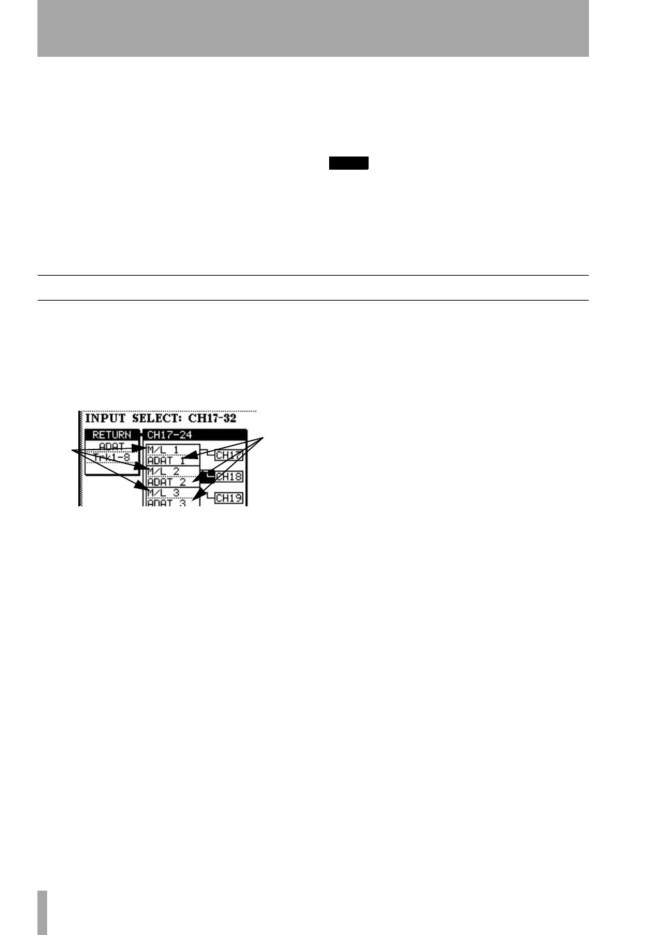
In the I/O assignment screens, each channel from 1
through 24 has two different sources—input and
return—available (channels 25 to 32 have only one
source—input—available):
In this illustration, the mic/line inputs are selected as
the inputs (upper box) for channels 17 through 24.
The ADAT connector audio is selected as the return
source (lower box) for these channels.
Sixteen mic/line analog inputs
are avail-
able on the DM-24. These are referred to on-screen
as
M/L
.
They may be assigned to the console channels num-
bered 1 through 32. These are inputs.
Three TDIF connectors
(1 through 3) carry
eight channels of I/O digital audio each (in base fre-
quency mode—in dual-frequency mode, this situa-
tion is different).
These TDIF inputs may also be assigned to console
channels numbered 1 through 24.
These are returns.
ADAT connector
The single “lightpipe” ADAT
input connector carries eight channels of digital
audio input.
The eight audio channels received through this con-
nector may be assigned to any of the console chan-
nels numbered 1 through 24.
These are returns.
DIGITAL IN 1 & 2
Each of these logical inputs has
two physical connectors: an XLR, typically used for
AES/EBU connections, and an RCA jack, typically
used for SPDIF connections. One of these can be
selected for each logical input, and routed to any of
the console channels numbered 1 through 32. These
are inputs.
Card slots
Optional cards may be installed in the
two card slots for expansion of the digital and analog
I/O. These are treated as returns, and may be routed
to the channels 1 through 24.
Assignable returns
These four balanced analog
inputs may be assigned as channel inputs (for exam-
ple, when they are used with external effect proces-
sors).
These are inputs and are assignable to channels 1
through 32.
Internal effectors
The DM-24 has two internal
digital effectors, with stereo returns.
These returns are inputs and are assignable to chan-
nels 1 through 32.
inputs
returns