Altera Arria 10 Avalon-ST User Manual
Page 62
Channel and Pin Placement for the Gen1, Gen2, and Gen3 Data Rates
The following figures illustrate the x1, x2, x4, and x8 channel and pin placements for the Arria 10 Hard IP
for PCI Express.
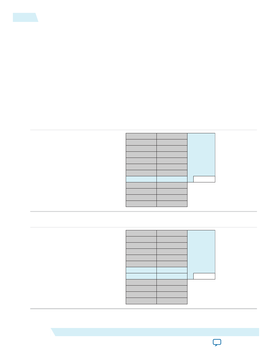
In these figures, channels that are not used for the PCI Express protocol are available for other protocols.
Unused channels are shown in gray.
Note: In all configurations, physical channel 4 in the PCS connects to logical channel 0 in the hard IP.
You cannot change the channel placements illustrated below.
For the possible values of
physical location of the Hard IP PCIe blocks in the different types of Arria 10 devices, at the start of this
chapter. For each HIP block, the transceiver block that is adjacent and extends below the HIP block, is
For example, in an Arria 10 device with 96 transceiver channels and four PCIe HIP blocks, if your design
uses the HIP block that supports CvP,
Figure 5-4: Arria 10 Gen1, Gen2, and Gen3 x1 Channel and Pin Placement
PMA Channel 5
PMA Channel 4
PMA Channel 3
PMA Channel 2
PMA Channel 0
PMA Channel 3
PMA Channel 2
PMA Channel 1
PMA Channel 0
PCS Channel 5
PCS Channel 4
PCS Channel 3
PCS Channel 2
PCS Channel 0
PCS Channel 3
PCS Channel 2
PCS Channel 1
PCS Channel 0
Hard IP Ch0
PMA Channel 1
PCS Channel 1
PMA Channel 4
PCS Channel 4
PMA Channel 5
PCS Channel 5
Hard IP
for PCIe
Figure 5-5: Arria 10 Gen1 Gen2, and Gen3 x2 Channel and Pin Placement
PMA Channel 5
PMA Channel 4
PMA Channel 3
PMA Channel 2
PMA Channel 0
PMA Channel 3
PMA Channel 2
PMA Channel 1
PMA Channel 0
PCS Channel 5
PCS Channel 4
PCS Channel 3
PCS Channel 2
PCS Channel 0
PCS Channel 3
PCS Channel 2
PCS Channel 1
PCS Channel 0
Hard IP Ch0
PMA Channel 1
PCS Channel 1
PMA Channel 4
PCS Channel 4
PMA Channel 5
PCS Channel 5
Hard IP
for PCIe
5-4
Channel and Pin Placement for the Gen1, Gen2, and Gen3 Data Rates
UG-01145_avst
2015.05.04
Altera Corporation
Physical Layout of Hard IP In Arria 10 Devices