Power management signals, Power management signals -54 – Altera Arria 10 Avalon-ST User Manual
Page 120
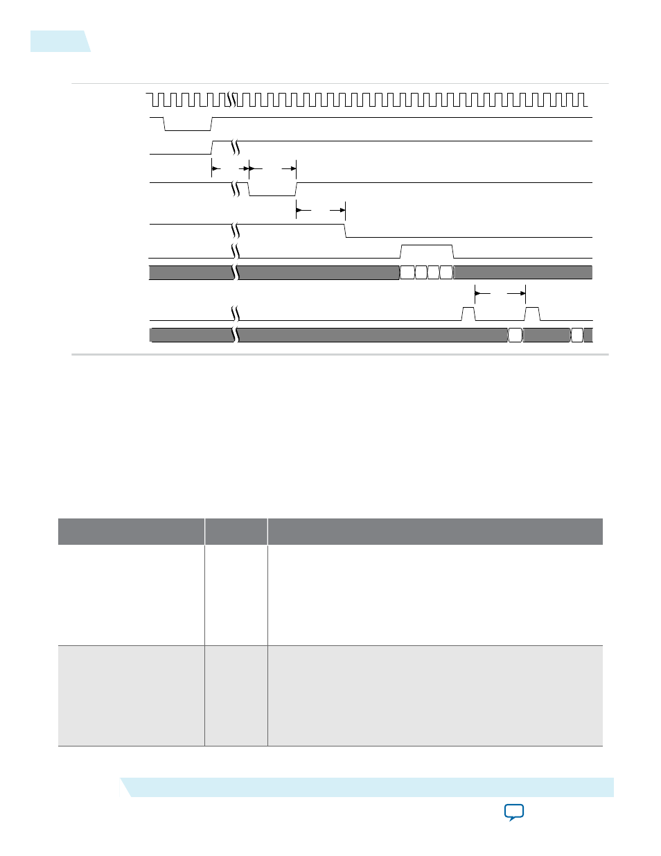
Figure 6-40: Hard IP Reconfiguration Bus Timing of Read-Only Registers
avmm_clk
hip_reconfig_rst_n
user_mode
ser_shift_load
interface_sel
avmm_wr
avmm_wrdata[15:0]
avmm_rd
avmm_rdata[15:0]
D0
D0
D1
D1
D2 D3
324 ns
4 clks
4 clks
4 clks
For a detailed description of the Avalon-MM protocol, refer to the Avalon Memory Mapped Interfaces
chapter in the Avalon Interface Specifications.
Related Information
Power Management Signals
Table 6-19: Power Management Signals
Signal
Direction
Description
pme_to_cr
Input
Power management turn off control register.
Root Port—When this signal is asserted, the Root Port sends the
PME_turn_off
message.
Endpoint—This signal is asserted to acknowledge the
PME_turn_
off
message by sending
pme_to_ack
to the Root Port.
pme_to_sr
Output
Power management turn off status register.
Root Port—This signal is asserted for 1 clock cycle when the Root
Port receives the
pme_turn_off
acknowledge message.
Endpoint—This signal is asserted for 1 cycle when the Endpoint
receives the
PME_turn_off
message from the Root Port.
6-54
Power Management Signals
UG-01145_avst
2015.05.04
Altera Corporation
Interfaces and Signal Descriptions