Altera Arria 10 Avalon-ST User Manual
Page 121
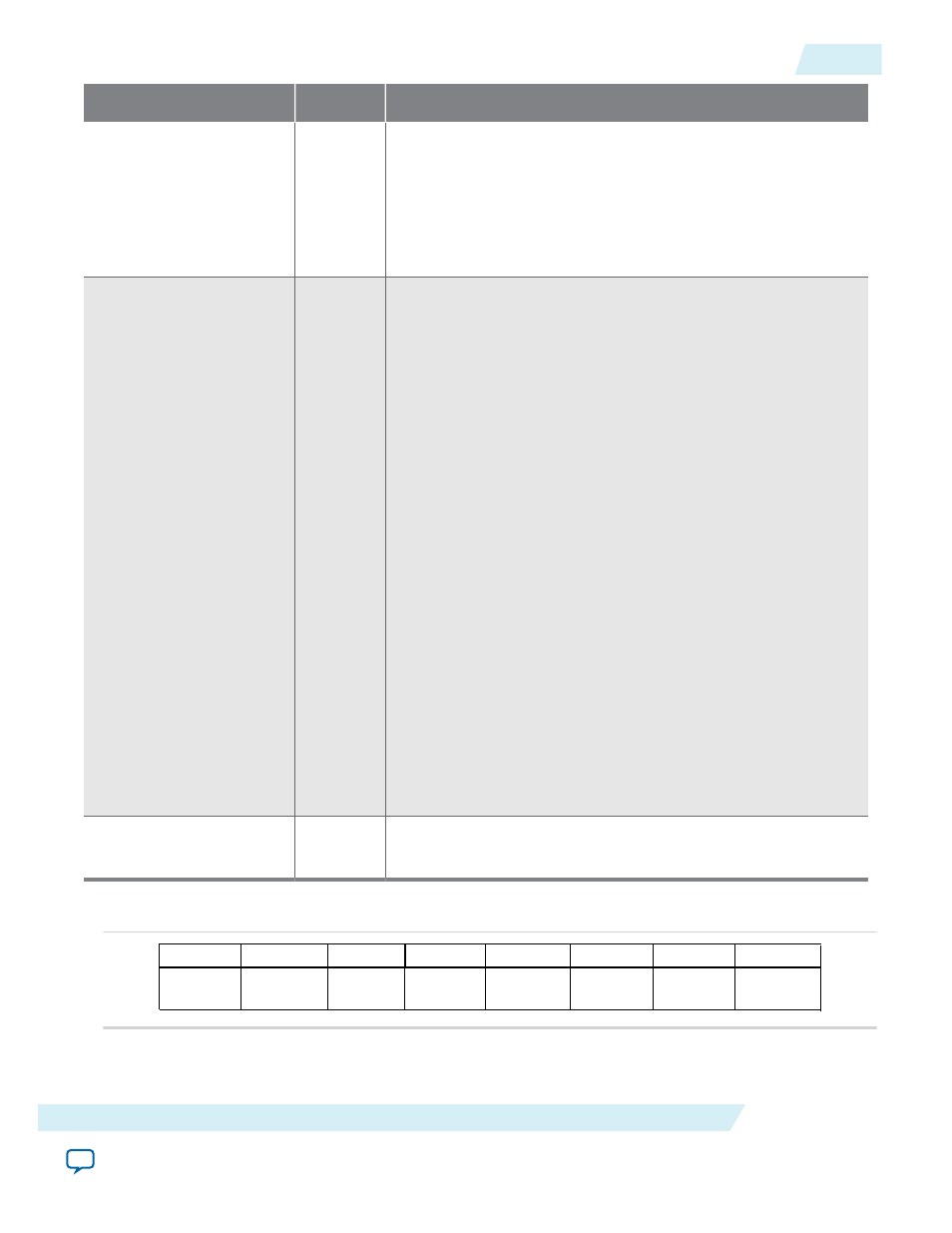
Signal
Direction
Description
pm_event
Input
Power Management Event. This signal is only available for
Endpoints.
The Endpoint initiates a a
power_management_event
message
(PM_PME) that is sent to the Root Port. If the Hard IP is in a low
power state, the link exits from the low-power state to send the
message. This signal is positive edge-sensitive.
pm_data[9:0]
Input
Power Management Data.
This bus indicates power consumption of the component. This
bus can only be implemented if all three bits of
AUX_power
(part
of the Power Management Capabilities structure) are set to 0.
This bus includes the following bits:
•
pm_data[9:2]
: Data Register: This register maintains a value
associated with the power consumed by the component.
(Refer to the example below)
•
pm_data[1:0]
: Data Scale: This register maintains the scale
used to find the power consumed by a particular component
and can include the following values:
• 2b’00: unknown
• 2b’01: 0.1 ×
• 2b’10: 0.01 ×
• 2b’11: 0.001 ×
For example, the two registers might have the following values:
•
pm_data[9:2]
: b’1110010 = 114
•
pm_data[1:0]
: b’10, which encodes a factor of 0.01
To find the maximum power consumed by this component,
multiply the data value by the data Scale (114 × .01 = 1.14). 1.14
watts is the maximum power allocated to this component in the
power state selected by the
data_select
field.
pm_auxpwr
Input
Power Management Auxiliary Power: This signal can be tied to 0
because the L2 power state is not supported.
Figure 6-41: Layout of Power Management Capabilities Register
data_select
data_scale
PM_state
PME_EN
PME_status
reserved
15
0
1
16
23
8
2
7
9
12
13
14
24
31
reserved
data
register
UG-01145_avst
2015.05.04
Power Management Signals
6-55
Interfaces and Signal Descriptions
Altera Corporation