Futaba 4PX 2.4GHz FASST T-FHSS S-FHSS User Manual
Page 24
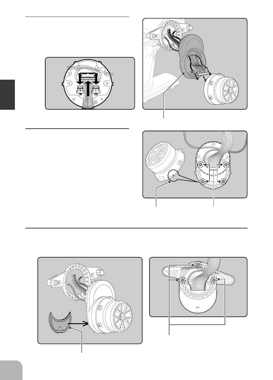
Marking
APA rear cover
Switch unit and APA mounting screws
(2.5x10mm tapping screws)
Wheel unit and APA mount-
ing screws (2.5x19mm tapping
screws)
Adapter APA
24
Bef
ore U
s
in
g
7
Using a Phillips screwdriver fasten the switch unit and APA. Use the 2.5x10mm tapping
screws in the accessories bag. Next, install the APA rear cover. Be careful that the length of
the screws is correct.
6
Using a Phillips screwdriver fasten the
wheel unit and APA at the desired angle
using the 2.5x19 tapping screws in the
accessory bag. Be careful that the screw
length is correct. Be careful that the wir-
ing does not get pinched. The angle can
be adjusted, but check the marking point
on the wheel unit and install the screws.
Screws can be installed at 4 places, but installation
at 4 places may be impossible due to the wheel
unit mounting angle.
5
Pass the wiring from the transmitter and
the charge unit wiring through the hole
in the APA as shown in the figure and
insert the 3 connectors at their original
positions on the wheel unit PC board.