Comtrol UP DeviceMaster User Guide User Manual
Page 23
DeviceMaster UP Modbus/TCP User Guide: 2000447 Rev. I
Chapter 2. Programming Interface - 23
Instance Attribute Definitions
Attribute 17
(Continued)
Receive
(DeviceMaster UP to
PLC) Ethernet Data
Transfer Method
•
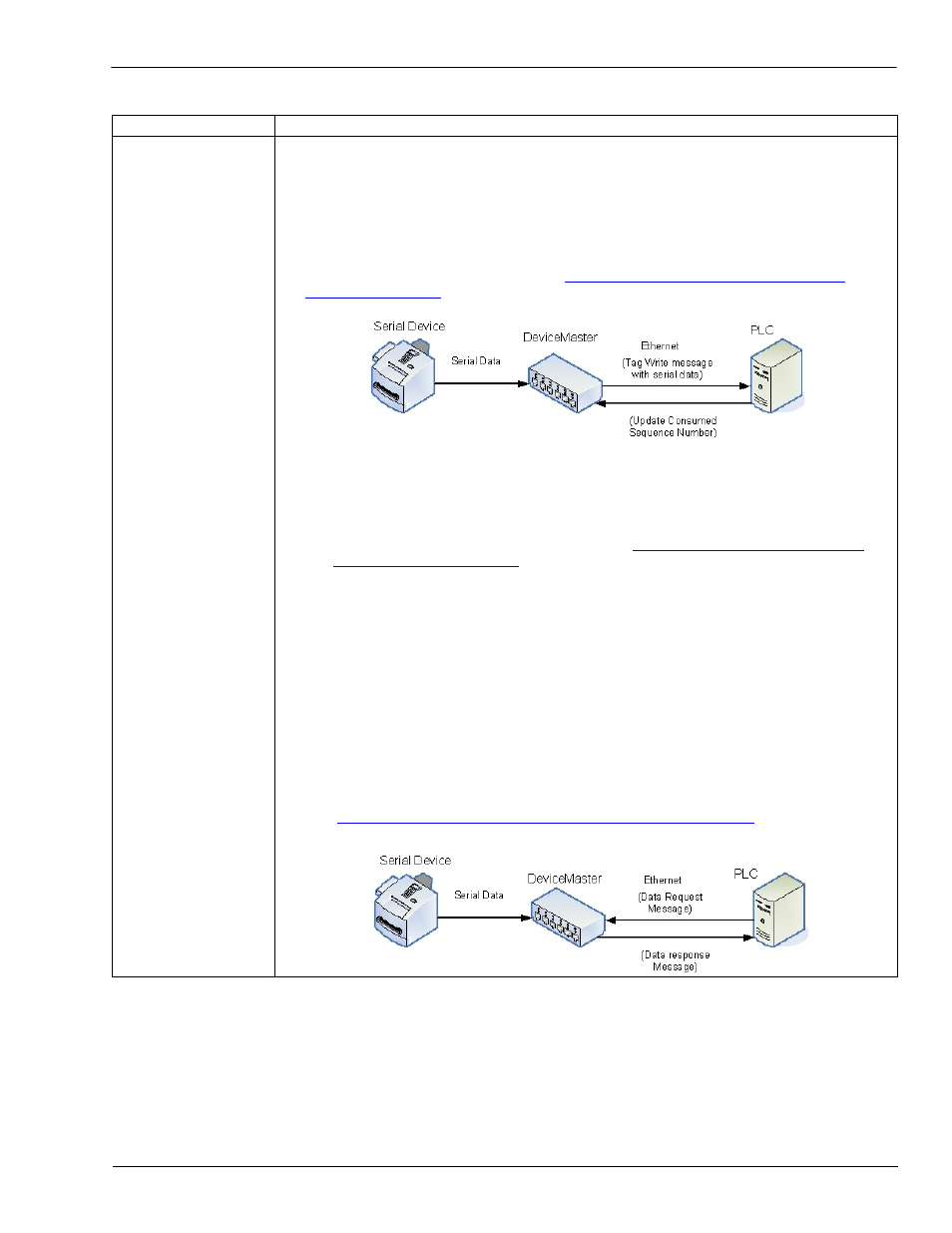
Unsolicited - Write-to-Tag-Synced receive method - DeviceMaster UP writes the
serial data into tag(s) on the PLC and provides a mechanism to synchronize the
data flow between the PLC and DeviceMaster UP.
In this method, DeviceMaster UP does not write the serial packet to the tag on the
PLC until the PLC updates the consumed sequence number (Serial Port Data
Transfer object Attribute 4) to match the produced data sequence number. Then
the DeviceMaster UP writes the data into the tag data location on the PLC in the
same way as the Unsolicited - Write-to-Tag receive method. For more information,
see the description of Attribute 4 in
2.3.2. Serial Port Data Transfer Object
on Page 29. The following diagram shows the Write-to-Tag-
Synced receive data flow:
The following restrictions apply to this method:
•
The Receive Data Area Tag Name (Attribute 24) must have the same name as the
tag defined on the PLC.
•
The tag on the PLC must be an SINT type and large enough to contain the
sequence number, length, and data field associated with the received data
structure. (For more information, see the
2.3.2. Serial Port Data Transfer
•
An incremented sequence number indicates new data.
•
The DeviceMaster UP does not write new data to the tag on the PLC until the
consumed sequence number has been incremented to match the last produced
sequence number.
•
While the DeviceMaster UP queues received serial port data, the PLC program
must consume the new data faster than the data can be received on the serial
port to ensure the receive buffers on the DeviceMaster UP do not overflow. (For
example: If the serial port can receive two serial packets per second, then the
consumption rate must be at least one packet every 500 microsecond.)
•
Polling receive method - The PLC requests data on a periodic basis.
In this method, DeviceMaster UP returns the serial data in the response to the
data request message. The PLC requests data by accessing the Serial Port Data
Transfer Object Attribute 2. For more information, see the description of Attribute
2 in
2.3.2. Serial Port Data Transfer Object Definition (71 Hex)
The following diagram shows the polling receive data flow:
Attribute
Description